
Rotational obstruction and beacon signaling apparatus

a technology of rotating obstruction and beacon signaling apparatus, which is applied in the direction of lighting support devices, lighting applications, identification means, etc., can solve the problems of limited visibility range, lack of long-term reliability of elements, and inability to treat them as point light sources, so as to enhance the luminous intensity of led signaling apparatus, improve heat dissipation, and improve the effect of thermal control

Inactive Publication Date: 2009-03-03
BWT PROPERTY
View PDF18 Cites 26 Cited by
  • Summary
  • Abstract
  • Description
  • Claims
  • Application Information

AI Technical Summary

Benefits of technology

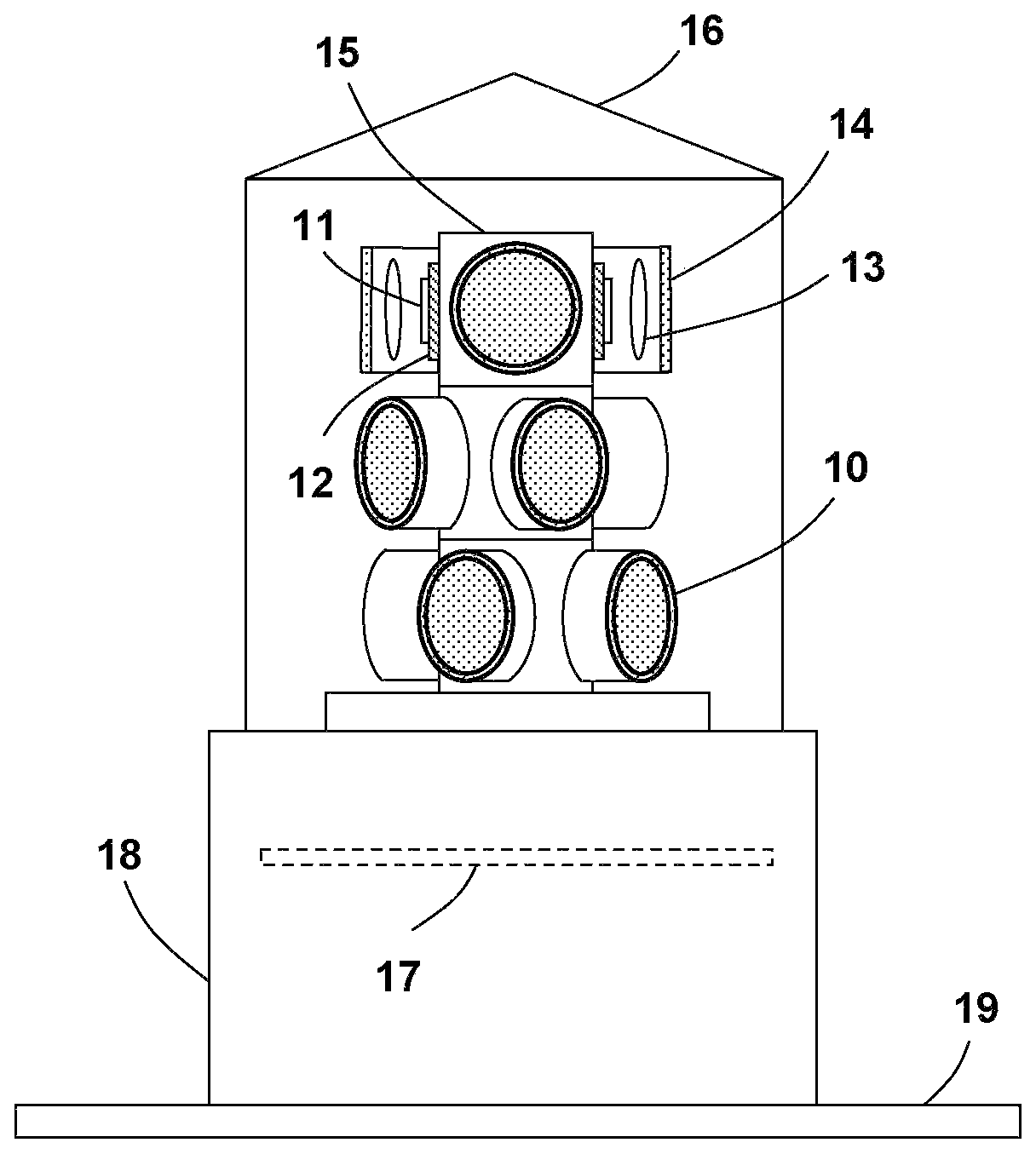
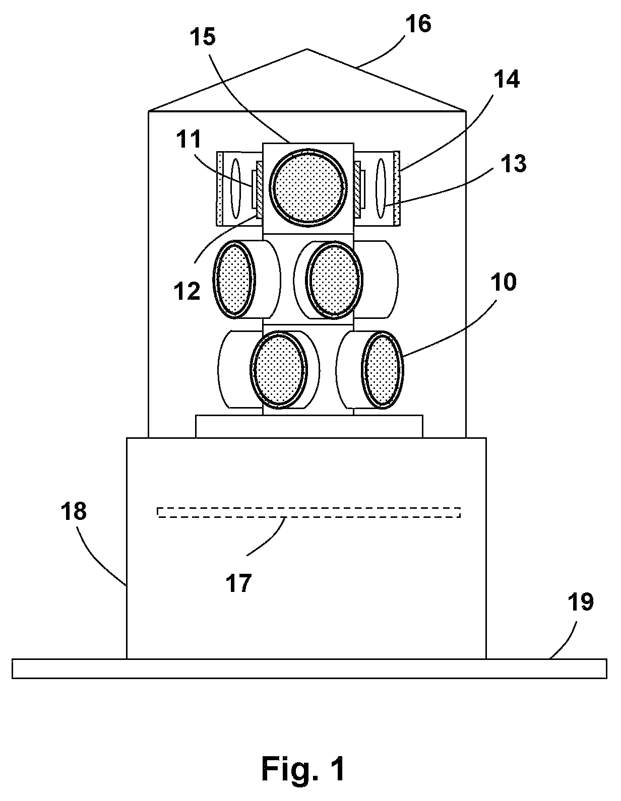
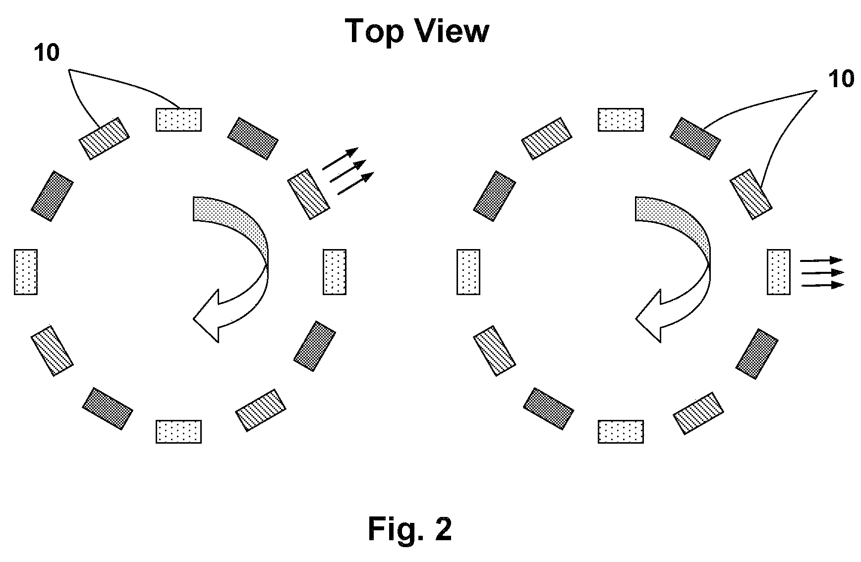
"The present invention is about an LED signaling apparatus that has enhanced luminous intensity and improved heat dissipation. The LED chips are surface mounted on a thermal conductive substrate for improved heat dissipation, which allows the LED to operate at much higher currents or output levels. The light beam produced by each LED unit is individually controlled by an optical beam transformer, which precisely defines its intensity distribution, divergence angle, and other relevant properties. The LED units can operate in a time sequenced flashing mode, which is controlled by an electronic timing circuit to simulate a rotational or other motional emission effect. The signaling apparatus comprises no mechanical moving parts, which enhances it long-term reliability."

Problems solved by technology

Thus they either are limited in visibility range or require a large number (several hundreds or even thousands) of LEDs to produce the desired luminous intensity.
In addition, some mechanical rotating elements are generally used to produce a rotational emission effect, which elements lack in long-term reliability.
Thus they can not be treated as point light sources.
This makes it extremely difficult for LED beam profile control.
This lens is both complicated in structure and difficult to manufacture.
In addition, such a lens design is not suitable to produce a rotational signaling effect since the divergence angle of the LED units can not be individually controlled.

Method used


Image

  • Rotational obstruction and beacon signaling apparatus
  • Rotational obstruction and beacon signaling apparatus
  • Rotational obstruction and beacon signaling apparatus

Examples


Embodiment Construction

[0013]Before describing in detail embodiments that are in accordance with the present invention, it should be observed that the embodiments reside primarily in combinations of method steps and apparatus components related to an LED based rotational obstruction and beacon signaling apparatus. Accordingly, the apparatus components and method steps have been represented where appropriate by conventional symbols in the drawings, showing only those specific details that are pertinent to understanding the embodiments of the present invention so as not to obscure the disclosure with details that will be readily apparent to those of ordinary skill in the art having the benefit of the description herein.

[0014]In this document, relational terms such as first and second, top and bottom, and the like may be used solely to distinguish one entity or action from another entity or action without necessarily requiring or implying any actual such relationship or order between such entities or actions...


PUM


Abstract

A rotational obstruction and beacon signaling apparatus, in which chip-on-board (COB) packaged light emitting diodes (LEDs) are employed to provide a flashed emission pattern with high luminous intensity. The flash sequence of individual LEDs is controlled by an electronic timing circuit to simulate a rotational or other motional signaling effect.

Description

REFERENCE TO RELATED APPLICATIONS[0001]This application claims an invention which was disclosed in Provisional Patent Application No. 60 / 596,631, filed Oct. 7, 2005, entitled “Rotational Obstruction and Beacon Signaling Based on High Brightness LED”. The benefit under 35 USC §119(e) of the above mentioned United States Provisional Applications is hereby claimed, and the aforementioned application is hereby incorporated herein by reference.FIELD OF THE INVENTION[0002]The present invention relates generally to a signaling apparatus, and more specifically to a rotational obstruction and beacon signaling apparatus based on high intensity light emitting diodes (LEDs).BACKGROUND[0003]Light emitting diodes (LEDs) are considered as an ideal replacement for incandescent lamps for warning and guidance signaling applications owing to their high wall-plug efficiency and long lifetime. The LED based warning and guidance signaling apparatus disclosed in prior arts employ traditional T-pack LED un...

Claims


Application Information

Patent Timeline
Patent Type & Authority Patents(United States)
IPC IPC(8): F21V21/00
CPCF21V5/002F21V5/04F21S10/06F21V23/0407F21W2111/00F21Y2101/02Y10S362/80F21Y2115/10F21S10/066
Inventor WANG, SEAN XIAOLU
Owner BWT PROPERTY
Learn More