Eureka AIR delivers breakthrough ideas for toughest innovation challenges, trusted by R&D personnel around the world.

Adjusting voltage for a phase locked loop based on temperature

a phase lock loop and voltage technology, applied in the field of integrated circuit devices, can solve the problems of inability to operate in extremely wide temperature ranges, inability to meet the intended use of cmos oscillators in high-frequency plls, and inability to meet military specifications (mil-specs) of 55 degrees celsius to +125 degrees celsius, so as to reduce the cost of operation, reduce the complexity of circuitry, and improve the yield of integrated circuit devices

Inactive Publication Date: 2009-02-17
GLOBALFOUNDRIES INC
View PDF13 Cites 8 Cited by
  • Summary
  • Abstract
  • Description
  • Claims
  • Application Information

AI Technical Summary

Benefits of technology

The patent describes a system and method for controlling the operation of integrated circuit devices, such as processors, using thermal sensors. By monitoring the temperature of the device, the system can adjust its operation to improve performance and reduce power consumption. The system includes a single set of thermal sensors that provide multiple functions, such as controlling the operation of the device, cooling system, and high-frequency circuitry. The thermal sensors sense the temperature and convert it to a digital value, which is used to determine the operating temperature of the device. The system can adjust the operation of the device based on the temperature to improve performance and reliability. The method can also include calibration information to compensate for changes in temperature. Overall, the system and method provide a way to optimize the performance and reliability of integrated circuit devices.

Problems solved by technology

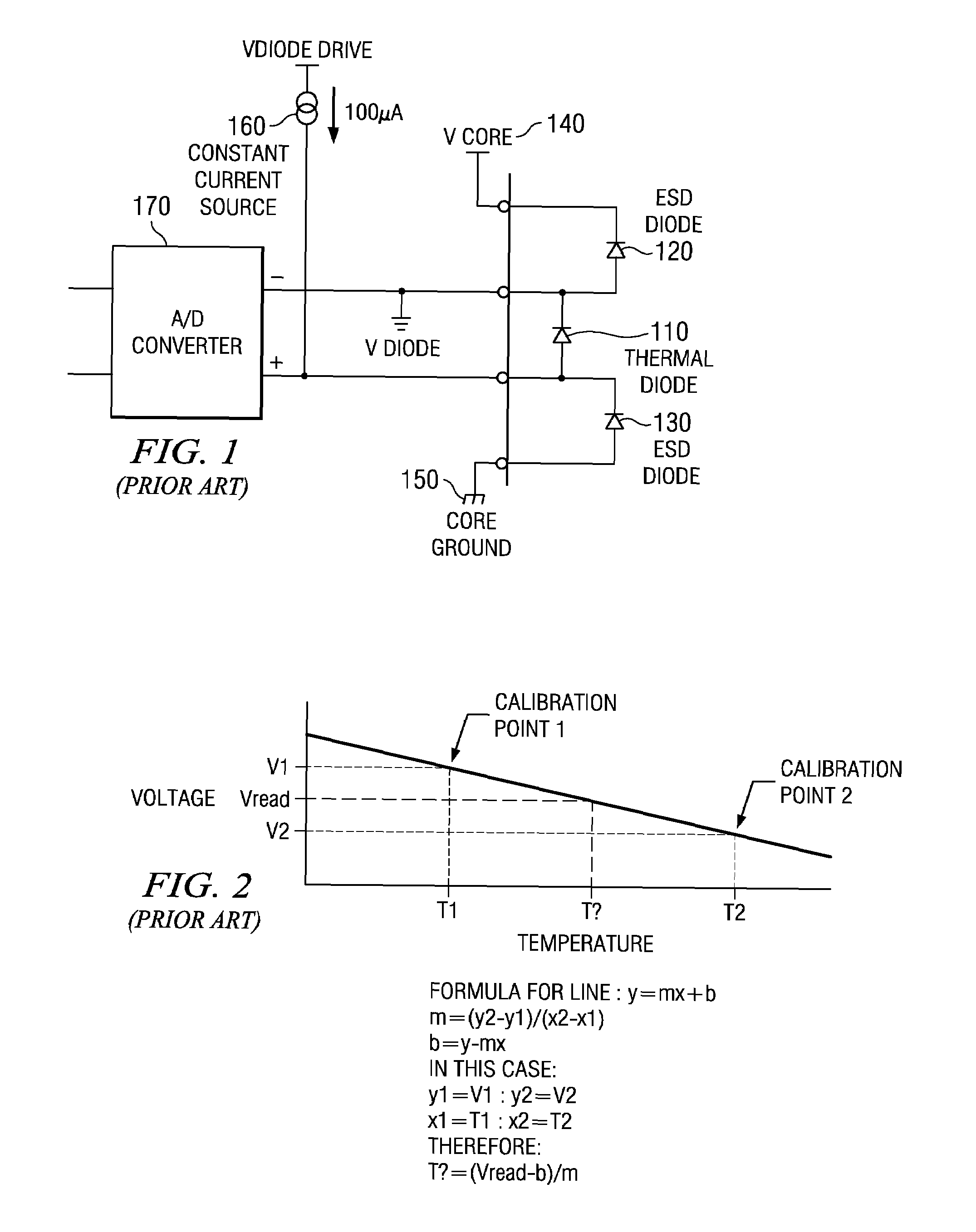
Variability of VCO frequency with respect to temperature, as well as process variation and voltage changes, can have a significant effect on performance, cost, and yield.
This temperature variability makes certain intended uses of these CMOS oscillators in high-frequency PLLs not feasible.
For example, operation in applications that require extremely wide temperature ranges, such as military specifications (mil-specs) of −55 degrees Celsius to +125 degrees Celsius may not be feasible.

Method used


Image

  • Adjusting voltage for a phase locked loop based on temperature
  • Adjusting voltage for a phase locked loop based on temperature
  • Adjusting voltage for a phase locked loop based on temperature

Examples


Embodiment Construction

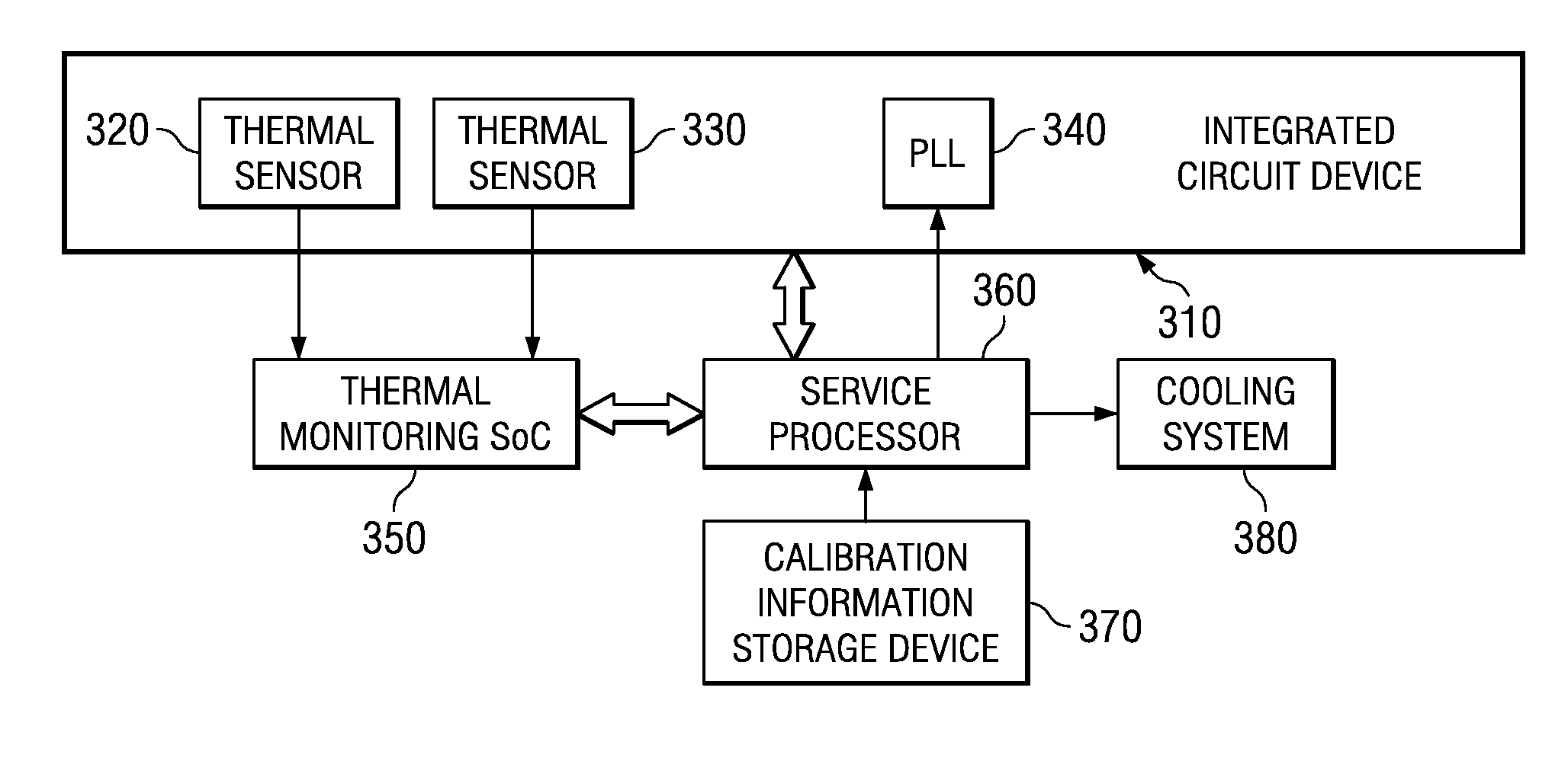
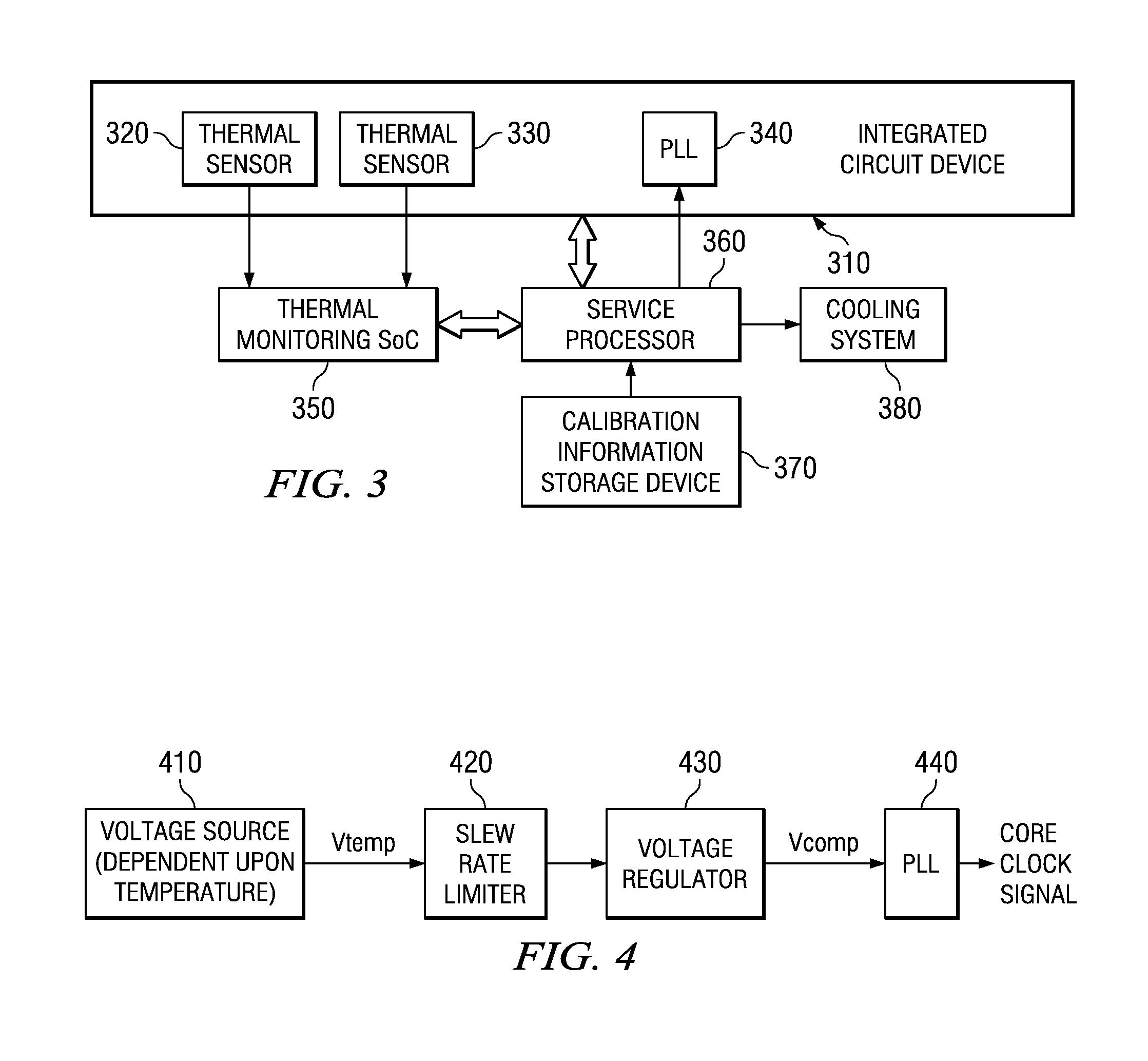
[0038]The illustrative embodiments provide an apparatus and method for controlling the operation of an integrated circuit device based on detected operating temperature of the integrated circuit device. The operation of the integrated circuit device is controlled in at least two ways: controlling the integrated circuit device in one or more different ways to attempt to reduce the operating temperature of the integrated circuit device, and controlling an operation of one or more phase locked loops (PLLs) of the integrated circuit device so as to compensate for temperature. A single set of one or more thermal sensors provided on the integrated circuit device is used to provide a measure of the operating temperature of the integrated circuit device which is then used to control the operating temperature and operation of the PLLs of the integrated circuit device. The illustrative embodiments will be described in terms of using thermal diodes as the one or more temperature sensors throug...


PUM

PropertyMeasurementUnit
temperatureaaaaaaaaaa

Abstract

A mechanism for utilizing a single set of one or more thermal sensors, e.g., thermal diodes, provided on the integrated circuit device, chip, etc., to control the operation of the integrated circuit device, associated cooling system, and high-frequency PLLs is provided. By utilizing a single set of thermal sensors to provide multiple functions, e.g., controlling the operation of the integrated circuit device, the cooling system, and the PLLs, silicon real-estate usage is reduced through combining circuitry functionality. Moreover, the integrated circuit device yield is improved by reducing circuitry complexity and increasing PLL robustness to temperature. Furthermore, the PLL circuitry operating range is improved by compensating for temperature.

Description

BACKGROUND[0001]1. Technical Field[0002]The present application relates generally to an integrated circuit device. More specifically, the present application is directed to a system and method for adjusting a voltage for a phase locked loop (PLL) based on temperature. The apparatus and method may be implemented in an integrated circuit device, such as a processor or the like, to both control cooling systems and the voltage of the PLL using a single thermal diode or temperature monitoring device.[0003]2. Description of Related Art[0004]Thermal diodes are often provided in integrated circuit devices to monitor the operating temperature of the integrated circuit device. The thermal diode measures the temperature of the integrated circuit device which is then monitored by a monitoring device, such as a monitoring circuit, system-on-a-chip, or the like, to control operation of the integrated circuit device and / or cooling systems, such as fans or other cooling systems. In this way, danger...

Claims


Application Information

Patent Timeline
Patent Type & Authority Patents(United States)
IPC IPC(8): G01K3/00G06F15/00
CPCH03L1/022H03L1/026H03L7/0995
Inventor BOERSTLER, DAVID W.CHADWICK, NATHANIEL R.HAILU, ESKINDERPETERSON, KIRK D.QI, JIEMING
Owner GLOBALFOUNDRIES INC
Why Eureka
Eureka Blog
Learn More