
EMI shields and related manufacturing methods

a manufacturing method and shield technology, applied in the direction of ceilings, conductors screwing into other parts, transmission, etc., can solve the problems of incomplete loss of important signals, inefficiency or inoperable of electronic equipment,

Inactive Publication Date: 2009-02-17
LAIRD TECH INC
View PDF62 Cites 30 Cited by
  • Summary
  • Abstract
  • Description
  • Claims
  • Application Information

AI Technical Summary

Benefits of technology

The present invention provides EMI shields that have a frame and a cover. The frame has peripheral walls with at least one folded portion forming an outer sidewall and an inner sidewall. The cover has a lid portion and edge portions with at least one dimple or opening. The cover is releasably retained to the frame by the engagement of the dimple with the opening. The method of making the EMI shield includes stamping a flat pattern partial profile for the frame and cover, forming bends and folded portions in the frame and cover, and removing the remaining material connecting the frame to the cover to form two separable frame and cover pieces. The technical effects of the invention include providing EMI shields with improved protection against electromagnetic interference and methods for making the shields with reduced labor and materials.

Problems solved by technology

Such EMI / RFI interference may originate from internal sources within the electronic equipment or from external sources.
Interference can cause degradation or complete loss of important signals, rendering the electronic equipment inefficient or inoperable.
Soldered shields, however, may need to be removed to repair or replace the covered component, which can be an expensive and time consuming task that can even cause damage to the PCB.

Method used


Image

  • EMI shields and related manufacturing methods
  • EMI shields and related manufacturing methods
  • EMI shields and related manufacturing methods

Examples


Embodiment Construction

[0023]The following description of the exemplary embodiments is merely exemplary in nature and is in no way intended to limit the invention, its application, or uses.

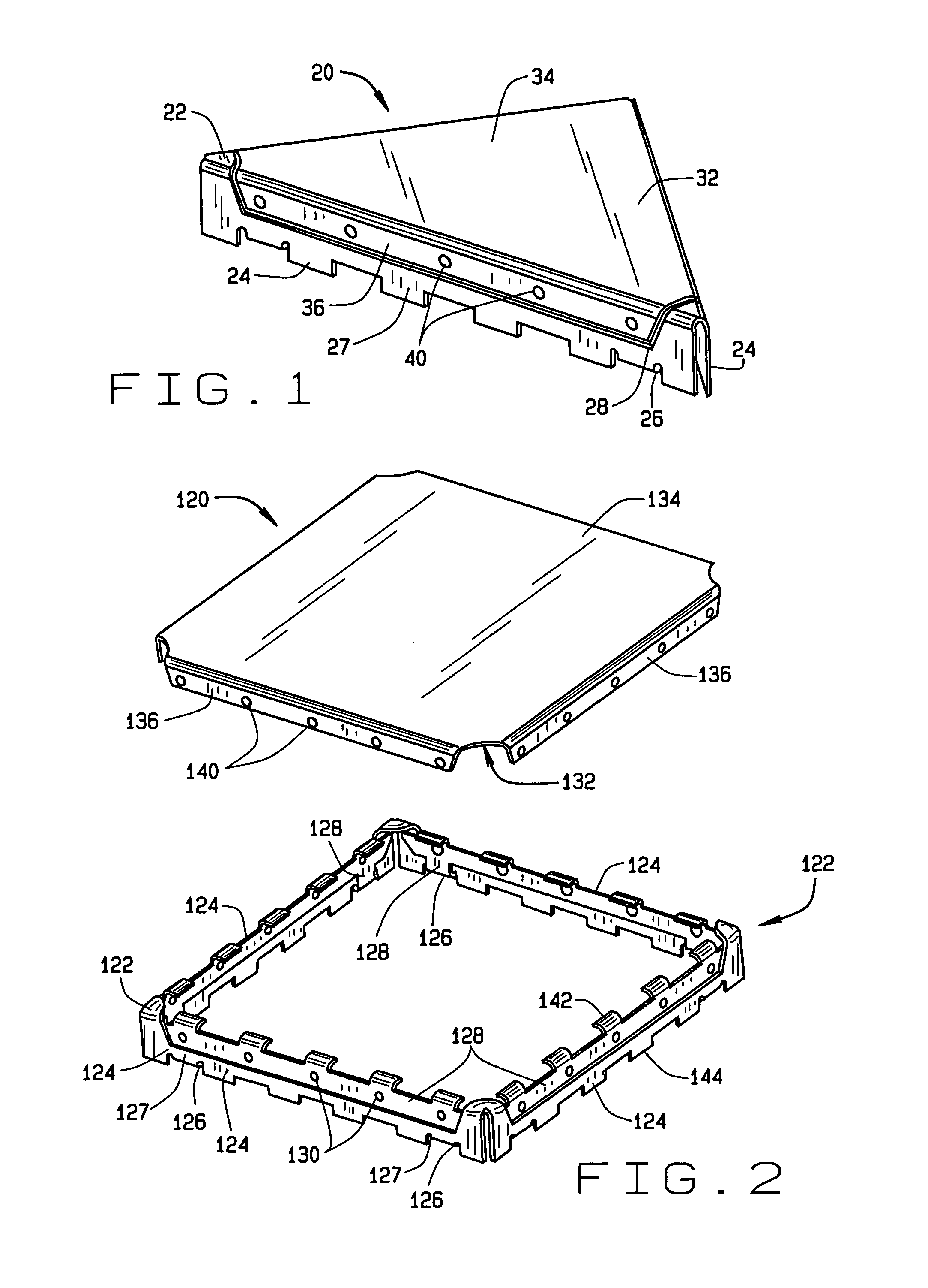
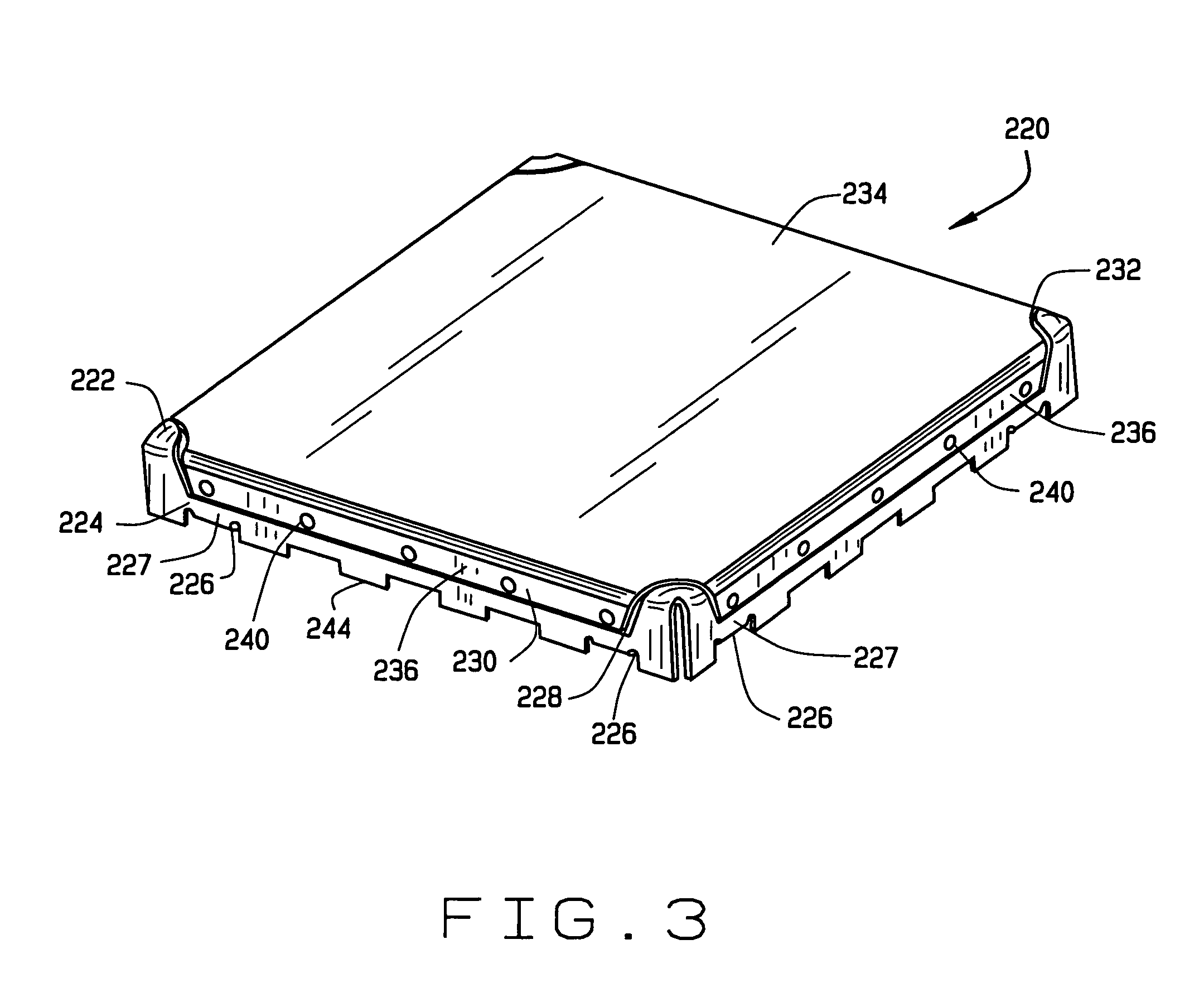
[0024]According to one aspect, the present invention provides EMI shields. In one particular embodiment, the EMI shield generally includes a frame and a cover. The frame includes peripheral walls each having at least one folded portion forming an outer sidewall and an inner sidewall. The cover includes a lid portion and a plurality of edge portions extending downwardly from the lid portion. The shield includes at least one dimple configured to be engagingly received in at least one opening for releasably retaining the cover to the frame.

[0025]According to another aspect, the present invention provides methods of making EMI shields. In one exemplary embodiment, a method generally includes stamping in a single piece of material a flat pattern partial profile for a frame and a cover. The profile for the frame includes havi...


PUM

PropertyMeasurementUnit
heightaaaaaaaaaa
heightaaaaaaaaaa
heightaaaaaaaaaa

Abstract

An electromagnetic interference (EMI) shield according to one embodiment generally includes a frame and a cover. The frame includes peripheral walls each having at least one folded portion forming an outer sidewall and an inner sidewall. The cover includes a lid portion and a plurality of edge portions extending downwardly from the lid portion. The shield includes at least one dimple configured to be engagingly received in at least one opening for releasably retaining the cover to the frame.

Description

FIELD OF THE INVENTION[0001]The present invention relates to multi-piece shields for shielding components on a printed circuit board from electromagnetic interference (EMI) / radio frequency interference (RFI).BACKGROUND OF THE INVENTION[0002]Electronic equipment may include electrical components and circuits mounted on a substrate that can be sensitive to electromagnetic interference (EMI) and radio frequency interference (RFI). Such EMI / RFI interference may originate from internal sources within the electronic equipment or from external sources. Interference can cause degradation or complete loss of important signals, rendering the electronic equipment inefficient or inoperable. Accordingly, the circuits (sometimes referred to as RF modules or transceiver circuits) should include EMI / RFI shielding in order to function properly. This shielding reduces interference not only from external sources, but also from various functional blocks within the module.[0003]Accordingly, electronic c...

Claims


Application Information

Patent Timeline
Patent Type & Authority Patents(United States)
IPC IPC(8): H01R4/56H05K9/00
CPCH04B1/40H04B15/00H05K9/0032Y10T29/4902Y10T29/49002
Inventor ZUEHLSDORF, ALLANVINOKUR, IGOR
Owner LAIRD TECH INC
Learn More