Carrierless electrophoresis process and electrophoresis device for carrying out this process

a carrierless electrophoresis and process technology, applied in the direction of fluid pressure measurement, liquid/fluent solid measurement, peptide measurement, etc., can solve the problems of linear flow rate cannot be reduced, sample throughput is difficult to optimize the electrophoresis device for its separation performance, and the linear flow rate is difficult to reduce, so as to improve the separation performance and reduce the separation time. , the effect of increasing the throughpu

Inactive Publication Date: 2009-02-17
BECTON DICKINSON & CO
View PDF95 Cites 2 Cited by
  • Summary
  • Abstract
  • Description
  • Claims
  • Application Information

AI Technical Summary

Benefits of technology

[0010]Consequently, an object on which the invention is based relates to creating a carrierless electrophoresis method and an electrophoresis device for carrying out this method, which allow for an increased separation performance, a shorter separation time and a greater throughput to be achieved.
[0012]An increase in the sample throughput in the first stage of coarse fractionation can be achieved by carrying out the separation process by means of FFE at an increased linear flow rate and with a simultaneously shortened migration path for the analytes to be separated. In this respect, the number of fractionation sites for coarse fractionation can be reduced considerably and a single fractionation site can be provided in the case that only one fraction is of interest. A further increase in the rate of sample throughput is possible if this two-stage process is carried out in the form of a parallel simultaneous multiple process.

Problems solved by technology

However, as in the case of most separation processes, a simultaneous optimization of the electrophoresis device with regard to its separation performance and the sample throughput is difficult.
In the case of FFE, simultaneous optimization is only possible within very narrow limits, as an increase in the quantity of the sample substance results in a reduction in the separation performance.
However, since the linear flow rate cannot be reduced at will, an extension of the separation time requires a corresponding increase in the length of the electrodes.
This in turn means that the outside dimensions of the separation chamber need to be increased simultaneously, making it difficult to manufacture the separation chamber gap with the desired accuracy.

Method used


Image

  • Carrierless electrophoresis process and electrophoresis device for carrying out this process
  • Carrierless electrophoresis process and electrophoresis device for carrying out this process
  • Carrierless electrophoresis process and electrophoresis device for carrying out this process

Examples


Embodiment Construction

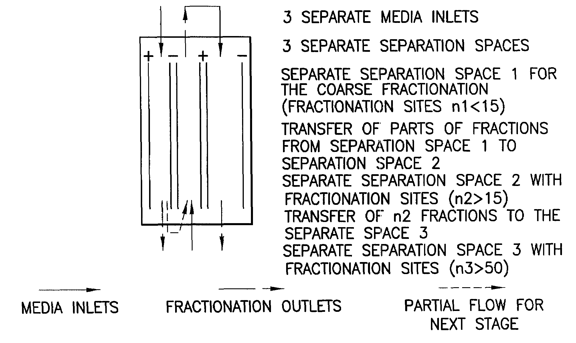
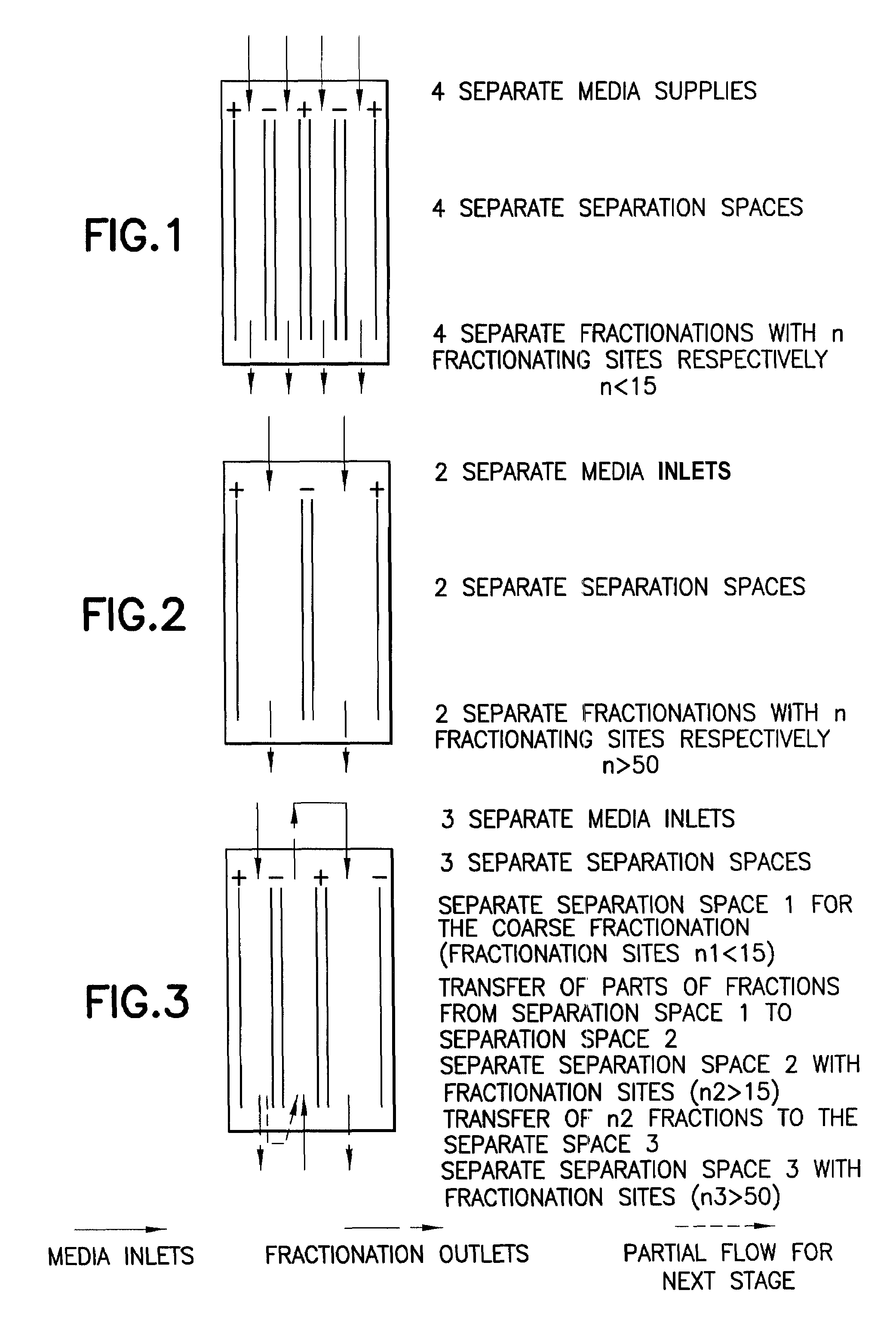
[0019]In FIGS. 1, 2 and 3, three examples of the separation chamber according to the invention are illustrated diagrammatically for different practical examples of the electrophoresis device. In order for the separation chamber to have an outside dimension which allows the separation chamber gap to be manufactured with sufficient accuracy, several separate separation spaces are provided in the separation chamber. According to FIG. 1, four separate separation spaces are provided with four separate media supplies for four separate fractionations with n fractionation sites, n being less than 15. FIG. 2 shows a separation chamber with two separate separation spaces and two separate media inlets for two separate fractionations with n fractionation sites, n being greater than 50. Finally, FIG. 3 shows a separation chamber with three separate separation spaces and three separate media inlets for two separate fractionations with n1 and n3 fractionation sites, n1 being less than 15 and n3 mo...


PUM

PropertyMeasurementUnit
Timeaaaaaaaaaa
Flow rateaaaaaaaaaa
Separationaaaaaaaaaa

Abstract

A free flow electrophoresis method for separating sample substances into their analytes. This method comprises multiple steps: a first step for the crude fractionation of the sample substance and at least one second step in which the crudely fractionated sample substance is finely fractionated. These steps can be performed in a parallel simultaneous method, in a serial method or in a combination of these two methods.

Description

[0001]This application is a 371 of PCT / EP01 / 14408, filed on Dec. 7, 2001, which claims priority from German application 10063097.9, filed on Dec. 18, 2000.BACKGROUND OF THE INVENTION[0002]1. Field of the Invention[0003]The invention relates to a carrierless electrophoresis method for separating sample substances into their analytes and an electrophoresis device for carrying out this method.[0004]2. Description of Related Art[0005]Known carrierless FFE electrophoresis methods commonly operate with electrophoresis devices whose separation chamber is equipped with only two separate electrode spaces and only one separation space between these electrode spaces.[0006]If, however, the FFE is to be used in the area of proteomics research, it must be possible to separate a large number of different sample substances within a short period, with a maximum separation output and with as high a rate of throughput of sample substances as possible.[0007]However, as in the case of most separation pr...

Claims


Application Information

Patent Timeline
IPC IPC(8): G01N27/447B01D57/02B03C5/00
CPCB01D57/02G01N27/44769G01N27/44773G01N27/447
Inventor WEBER, GERHARD
Owner BECTON DICKINSON & CO
Why Eureka
Try Eureka