
Flow damper

a flow damper and damper technology, applied in the field of flow dampers, can solve the problems of deteriorating the slide of the piston, the inability to adjust the flow damper, and the decrease of the valve body and the piston, so as to avoid the deterioration of the piston slide and facilitate the flow adjustmen

Active Publication Date: 2009-02-10
DENSO CORP
View PDF5 Cites 5 Cited by
  • Summary
  • Abstract
  • Description
  • Claims
  • Application Information

AI Technical Summary

Benefits of technology

[0015]The present invention addresses the above disadvantages. Thus, it is an objective of the present invention to provide a flow damper, which avoids deterioration of piston slide when a valve body is fastened to a rail main body using strong axial force, and which facilitates flow adjustment.

Problems solved by technology

When the valve body is strained for the above reason and accordingly the piston sliding hole is deformed in a radially inward direction, a sliding clearance between the valve body and the piston is decreased, thereby deteriorating a slide of the piston.
However, since the stopper J3 is press-fitted into the valve body J3 in a production process of the flow damper, a fuel flow cannot be adjusted in the flow damper, which has been produced.

Method used


Image

  • Flow damper
  • Flow damper
  • Flow damper

Examples


first embodiment

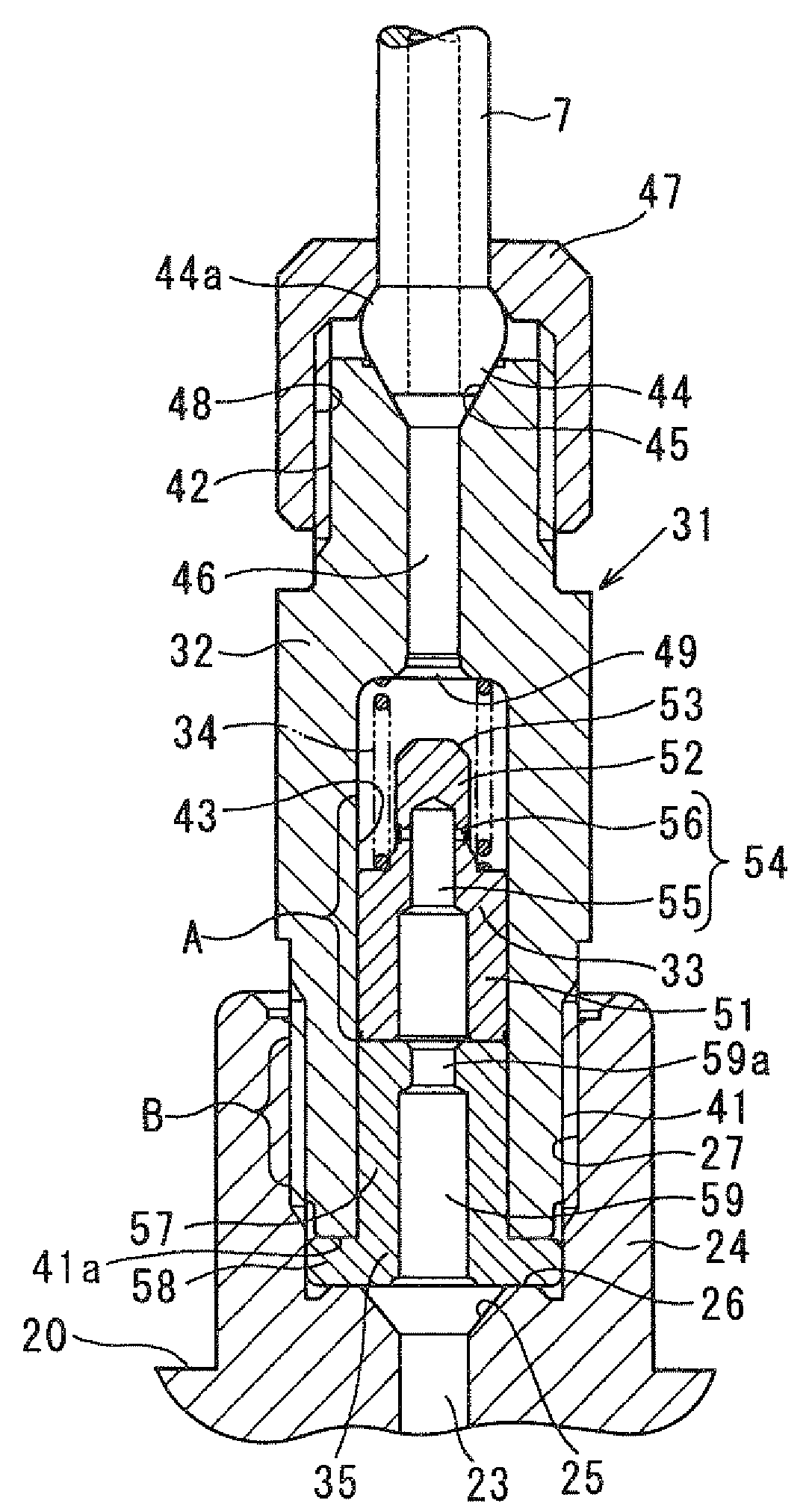
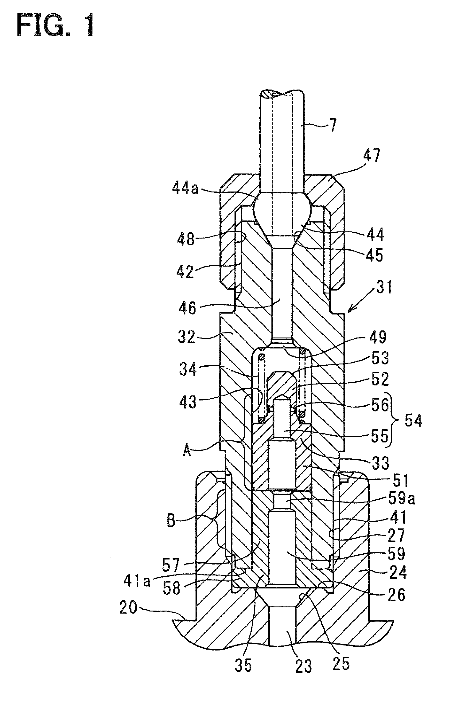
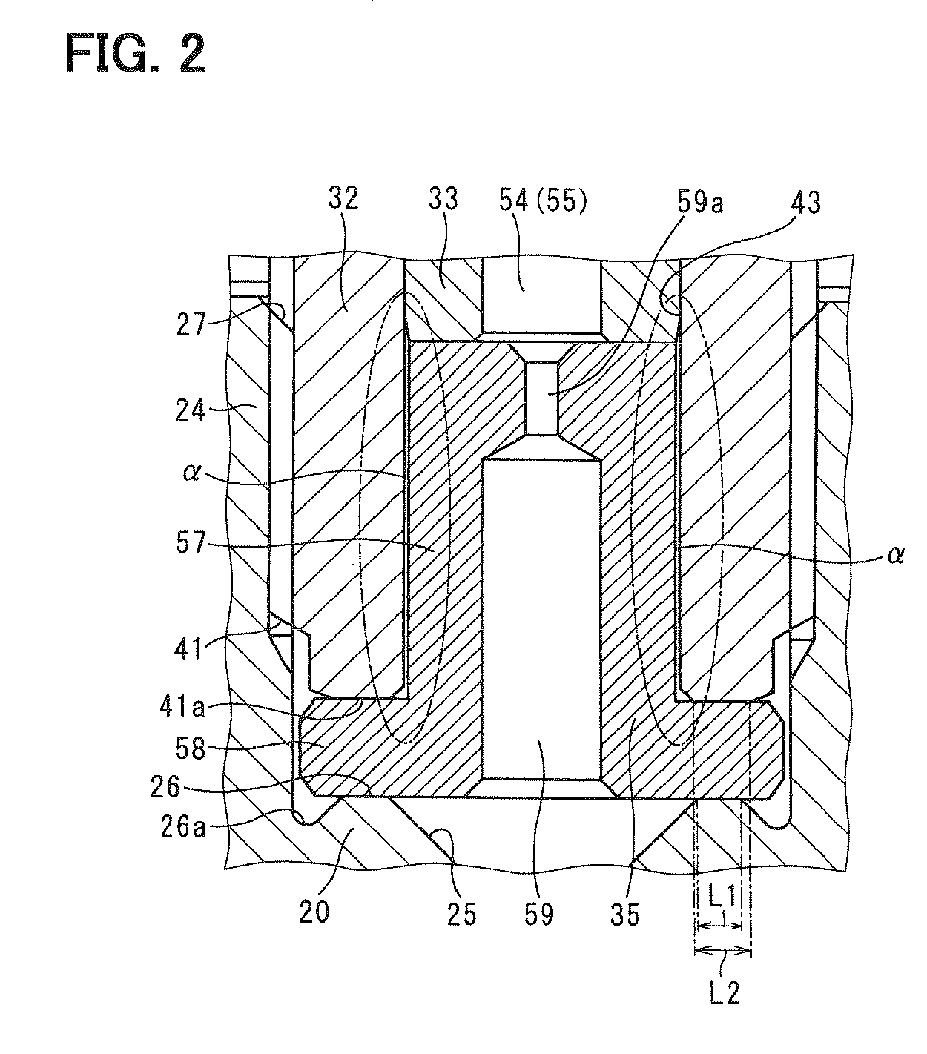
[0029]In the first embodiment, an example of a common-rail fuel injection system is described with reference to FIG. 3, and after that, a flow damper is explained with reference to FIGS. 1, 2.

(Common-rail Fuel Injection System)

[0030]The common-rail fuel injection system in FIG. 3 injects fuel into each cylinder of an engine, which is a diesel engine (not shown), for example. The common-rail fuel injection system includes a common rail 1, injectors 2, a supply pump 3, an engine electronic control unit (ECU) 4, and an electronic driver unit (EDU) 5.

[0031]The common rail 1 is a pressure accumulating container for accumulating pressure of high-pressure fuel, which is supplied to the injectors 2. The common rail 1 is connected to a discharge outlet of the supply pump 3, which force-feeds high-pressure fuel through a high-pressure pump pipe 6 in order to accumulate common rail pressure corresponding to fuel injection pressure. The common rail 1 is also connected to injector pipes 7, which...

second embodiment

[0092]A second embodiment of the present invention is described below with reference to FIGS. 4A, 4B. In the second embodiment, the same numeral as the first embodiment indicates the same component.

[0093]In the above first embodiment, as shown in FIG. 4B, the orifice 59a is formed in an upper end portion (on a piston 33-side) of the cap 35.

[0094]In the second embodiment, as shown in FIG. 4A, an orifice 59a is formed in a lower end portion (on a rail main body 20-side) of a cap 35.

[0095]By forming the orifice 59a in this manner as well, a similar effect to the first embodiment is produced.

[0096]More specifically, an upper chamfered portion of the orifice 59a is formed by a conical portion at an end of a drill bit, which forms a communicating portion 59. Accordingly, only a lower chamfered portion exposed outside needs to be chamfered. Similar to the first embodiment, the chamfering is easily performed, and thereby the cost rise caused by the chamfering is restricted.

[0097]Because the...


PUM


Abstract

A flow damper includes a valve body, a piston, a spring, and a cap. The valve body is fastened to the rail main body and has a fuel passage therein. The fuel passage communicates between a fuel hole of the rail main body and the injector. The fuel passage includes a piston sliding hole on its rail main body-side. The piston is slidably held on an inner circumferential surface of the piston sliding hole. The spring urges the piston in an opposite direction from a direction of fuel flowing through the fuel passage. The cap includes a small diameter portion and a large diameter portion. The small diameter portion is fitted into the inner circumferential surface of the piston sliding hole with a gap between the small diameter portion and the piston sliding hole. The large diameter portion is located between the valve body and the rail main body.

Description

CROSS REFERENCE TO RELATED APPLICATION[0001]This application is based on and incorporates herein by reference Japanese Patent Application No. 2006-353241 filed on Dec. 27, 2006, and Japanese Patent Application No. 2007-251921 filed on Sep. 27, 2007.BACKGROUND OF THE INVENTION[0002]1. Field of the Invention[0003]The present invention relates to a flow damper.[0004]2. Description of Related Art[0005]A flow damper includes a valve body, a piston, a spring, and a stopper The valve body has a generally cylindrical shape, and a fuel passage is formed in the valve body. The piston slides in its axial direction along a piston sliding hole formed inside the valve body. The spring urges the piston toward an upstream side in a fuel flow direction. The stopper restricts displacement of the piston toward the upstream side (see, for example, JP2001-50141A corresponding to U.S. Pat. No. 6,357,415).[0006]The piston has a throttle passage, which communicates between upstream and downstream sides of ...

Claims


Application Information

Patent Timeline
Patent Type & Authority Patents(United States)
IPC IPC(8): F02M55/02F02M55/04
CPCF02M55/025F02M55/04F02M63/0225F02M2200/28Y10T137/7773
Inventor OCHIAI, HIROAKI
Owner DENSO CORP
Learn More