
Device for the dosing of a reducing agent

a technology of reducing agent and device, which is applied in the direction of lighting and heating apparatus, combustion types, separation processes, etc., can solve the problems of large metering system and complicated production

Inactive Publication Date: 2009-01-27
ROBERT BOSCH GMBH
View PDF15 Cites 33 Cited by
  • Summary
  • Abstract
  • Description
  • Claims
  • Application Information

AI Technical Summary

Benefits of technology

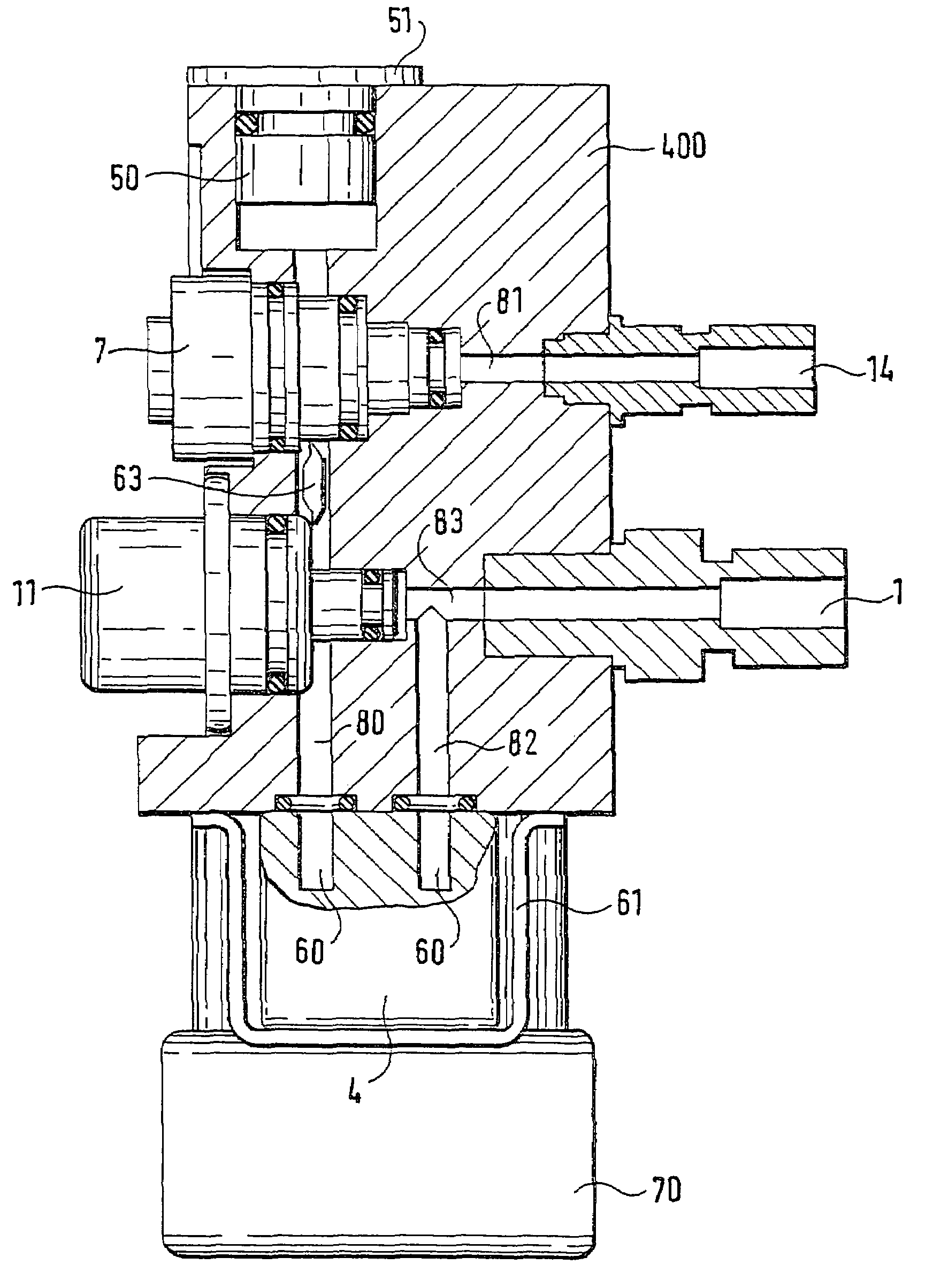
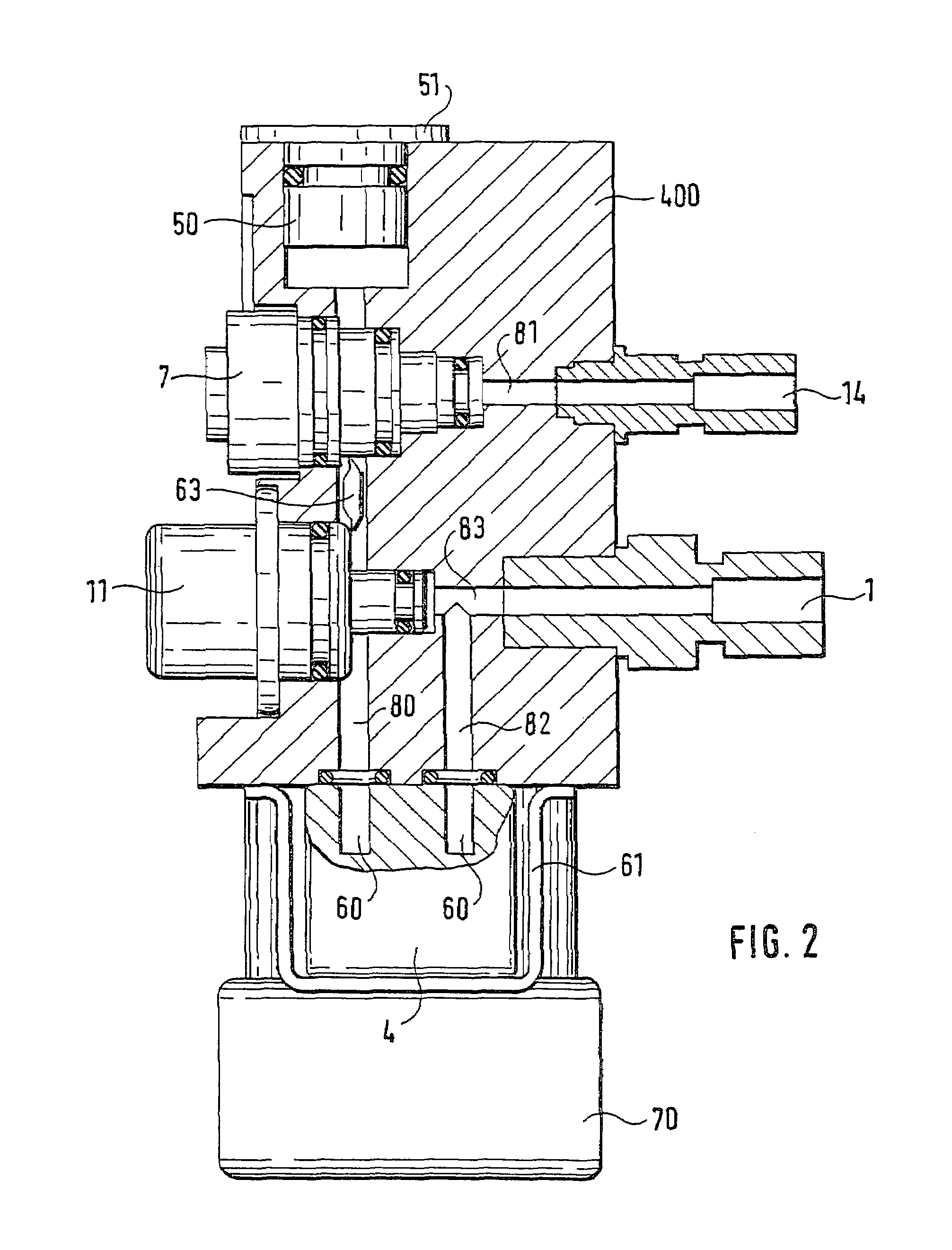
[0007]The metering apparatus of the invention has the advantage over the prior art of a simple, sturdy line layout with a minimum number of sealing points, which can be produced economically and in large-scale mass production. Since there are only a few sealing points, there is less risk of leaks and therefore less risk of failure. Hoses and separate screw fastenings for lines can be omitted. Because of the smaller number of required components and the smaller structural size, the effort and expense of assembly is less, the overall structural volume is decreased, and the production and system costs are thus lowered. The structural unit can be checked for tightness, for instance, after preassembly, which means reduced rejection costs compared to finding defects upon final system checking. The recesses can be disposed in various ways, for instance in the form of bores; additional bores make it possible to expand the basic functions of the metering apparatus by mounting additional components. The provision of recesses in a housing block makes it possible to attach the metering means and other function components to the housing block; the length of the line filled with reducing agent is kept short as a result, so that the liquid can be rapidly thawed again after ice forms. Short line layouts are also fast to fill, and the requisite pressure for operation can be built up quickly.
[0008]It is especially advantageous for all the means to be connected to one another via at least one rectilinear supply line that traverses the entire housing block. This line layout is simple to produce and makes possible an adroit arrangement of components that have to be connected to one another. Moreover, it can be embodied in a simple way as an injection-molded bore, for instance in a plastic block that receives the various system components.
[0010]A heating element, introduced in particular axially parallel to the recess, such as an electric heating rod embodied as an electrical resistor, can advantageously heat a central line quickly in order to thaw a frozen fluid or to protect the apparatus from freezing. Alternatively, or in combination with the electric heating rod, the housing block can also comprise an electrically conductive material, in particular an electrically conductive plastic, which as described in German Patent Application 199 46 900.8, is provided with electrodes that can be subjected to an electrical voltage, in order to achieve an electric current for heating the entire assembly by way of the housing block.
[0012]It is also advantageous to integrate compensatory or resilient elements in the assembly, so that a freeze-resistant metering system can be furnished that remains intact after freezing and thawing cycles and that protects integrated components against destruction from ice formation. The individual components themselves need not be embodied as completely freeze-resistant. Moreover, materials that are not resistant to high pressure can also be used, in particular for the housing block, since the buildup of excessive pressure forces in such extreme situations as freezing is averted.

Problems solved by technology

The metering system described is relatively large and complicated to produce, since it comprises a plurality of components located in line with one another.

Method used


Image

  • Device for the dosing of a reducing agent
  • Device for the dosing of a reducing agent
  • Device for the dosing of a reducing agent

Examples


Embodiment Construction

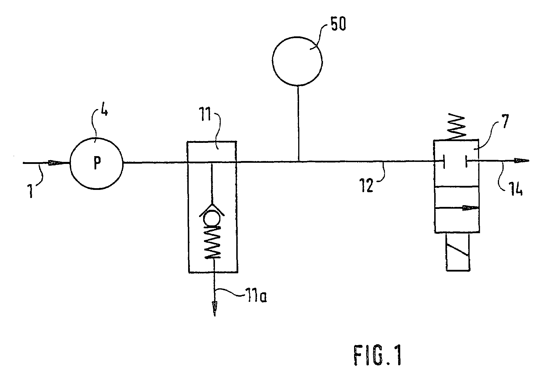
[0018]In FIG. 1, reference numeral 1 indicates the inlet to the metering apparatus, by way of which a urea-water solution is supplied to the apparatus. A metering pump 4 aspirates the fluid. The pump 4 is rpm-controlled via a stepping motor, not shown. A pressure regulator 11 carries any excess pumped quantity of fluid via the outlet 11a of the pressure regulator either back to the inlet of the metering apparatus or to the metering pump or to a urea tank, not shown in detail, from which the metering pump 4 is supplied via the inlet 1. The line 12 connecting the inlet 1, pump 4 and pressure regulator 11 carries the pumped fluid onward to a metering valve 7. A pressure sensor 50 for measuring the pressure in the line 12 is mounted upstream of the metering valve. The metering valve is electrically triggerable and dispenses the fluid in accordance with the electrical triggering to components connected to the outlet 14. This is for example a mixing chamber, not shown in detail but alread...


PUM

PropertyMeasurementUnit
volumeaaaaaaaaaa
elasticaaaaaaaaaa
pressureaaaaaaaaaa

Abstract

An apparatus for metering a urea or a urea-water solution for delivery to a catalytic converter assembly for removing nitrogen oxides from the exhaust gases of a Diesel engine, includes a housing block supporting function components communicating via a line, formed by recesses in the housing block, for transporting the reducing agent, and the walls of the line are formed by the housing block. This apparatus assures a simple line layout for reducing agent with a minimum number of sealing points that is accordingly appropriate for large-scale mass production.

Description

CROSS-REFERENCE TO RELATED APPLICATIONS[0001]This application is a 35 USC 371 application of PCT / DE 01 / 03663 filed on Sep. 24, 2001.BACKGROUND OF THE INVENTION[0002]1. Field of the Invention[0003]The invention is based on an apparatus for metering a reducing agent, in particular a urea or a urea-water solution, in the context of catalytic posttreatment of exhaust gases.[0004]2. Description of the Prior Art[0005]To achieve a reduction in NOx components in exhaust gases, reduction catalytic converters have been developed, especially for Diesel engines, and are typically classified as either so-called SCR catalytic converters (for Selective Catalytic Reduction) or reservoir-type catalytic converters. The so-called SCR catalytic converters are regenerated by delivering a reducing agent comprising urea and / or ammonia, while the so-called reservoir-type catalytic converters are regenerated in so-called rich exhaust gas phases with hydrocarbons from the entrained internal combustion engine...

Claims


Application Information

Patent Timeline
Patent Type & Authority Patents(United States)
IPC IPC(8): F01N7/00F01N3/08B01D53/94F01N3/20
CPCF01N3/2066F01N3/36F01N2610/02F01N2610/10F01N2610/14F01N2610/1433F01N2610/1446Y02T10/24Y02T10/12F01N3/20
Inventor HUBER, SVENMAYER, HANSPETERMUELLER, GERHARDOFFENHUBER, MICHAELMOELL, LEGAL REPRESENTATIVE, HELMUTMOELL, LEGAL REPRESENTATIVE, BRIGITTEMOELL, ALEXANDER
Owner ROBERT BOSCH GMBH
Learn More