
Converting a digital radiograph to an absolute thickness map

a digital radiograph and absolute thickness technology, applied in the field of radiographic imaging systems, can solve the problems of piping and vessel infrastructure mechanical as well as chemical degradation, and the environment in which they reside can be quite hostile, and achieve the effects of reducing the number of instruments, and improving the accuracy of the imag

Active Publication Date: 2009-01-20
BL TECH INC
View PDF31 Cites 54 Cited by
  • Summary
  • Abstract
  • Description
  • Claims
  • Application Information

AI Technical Summary

Benefits of technology

The patent describes a system and method for taking digital images of a physical structure using X-rays and transforming them into an absolute thickness map of the object. The system calibrates the data to account for variations in X-ray paths, detector response, and the object's geometry and material composition. The calibration procedure can be used with both isotopic and X-ray tube sources. The technical effect is the ability to accurately measure the thickness of objects using a non-destructive method.

Problems solved by technology

In installations, such as oil and gas fields, power stations, petrochemical plants, etc., the fluids and the environments in which they reside can be quite hostile.
High temperatures and pressures exist in the presence of volatile, toxic, and corrosive chemical mixtures.
As these substances are transported throughout a plant, they can cause both mechanical as well as chemical degradation of the piping and vessel infrastructure.
The damage is seen in terms of physical material loss due to corrosion and erosion or a weakening of the infrastructure due to increased stress.
Processes which cause material loss, degrade the structural and mechanical integrity of plants.
However, these standards are not aimed at maintaining peak operating efficiency of the plant, nor are they specified to ensure maximal up-time for plant operations.
However, a fully condition-based maintenance program is difficult to deploy owing to the lack of availability of a complete quantitative survey of asset conditions.
Furthermore many of the different inspection and monitoring modalities utilized in evaluating the fitness for service of a plant are unable to give a quantitative assessment of condition over large areas.
However, UT technology is in general limited to measurements over areas of point like dimensions.
While this is sufficient for uniform general corrosion, localized corrosion and damage mechanisms that can produce such features as deep narrow pits and steep gradients of material erosion, are difficult to detect and measure accurately without the use of an imaging based modality.
However, this fundamental technique is still a contact modality and is thus restricted to materials, and conditions, that support transmission of acoustic energy.
UT measurements are sometimes difficult to deploy since a good acoustic coupling must be made between the transducer and the material under inspection.
Furthermore, piping that is insulated is quite often at an elevated temperature, and UT sensors may not be able to function efficiently under such conditions.
Another problem with acoustic inspection methods is that multiple measurements must be made of the identical region over an extended period of time in order to track the evolution of these defects.
These measurements have significant compromises in the ultimate precision that can be attained, and such measurements cannot be made in real-time in order to correlate with plant operating conditions.
However it is almost impossible to correlate coupons with specific plant operating conditions in real-time or to identify small regions of enhanced or accelerated corrosive activity.
This technique is sensitive to conditions which are generally integrated over long time scales, and large areas.
Specific information about small areas are not monitored well with this technique.
Furthermore, unlike the other non-destructive testing (NDT) methods, installation and extraction of a coupon is an intrusive measurement.
Film based radiography systems suffer from a different problem.
Although the raw data captured in a radiograph gives information over an extended area, it has been very difficult to extract quantitative information from the gray scale shading or rendering from a piece of film.
Furthermore, the small dynamic range of film means that wide variations in material thickness cannot be imaged effectively in single exposures.
Quantification of this effect is very difficult.
Unfortunately this technique is restricted to extracting the wall thickness at the position perpendicular to the tangent of the pipe, and a complete series of shots need be taken to cover the complete area of the pipe, for example as described in U.S. Pat. No. 6,377,654.
However the precision and accuracy of such a procedure is compromised in all but the most simple cases where the impulse (or thin material) approximation is valid.
However, limitations still exist in the application of radiography to extract precision absolute measurements on thicknesses over large areas.

Method used


Image

  • Converting a digital radiograph to an absolute thickness map
  • Converting a digital radiograph to an absolute thickness map
  • Converting a digital radiograph to an absolute thickness map

Examples


Embodiment Construction

[0031]The exemplary embodiments of the present invention will be described below with reference to the accompanying drawings. In the following description, well known functions or constructions are not described in detail to avoid obscuring the invention in unnecessary detail.

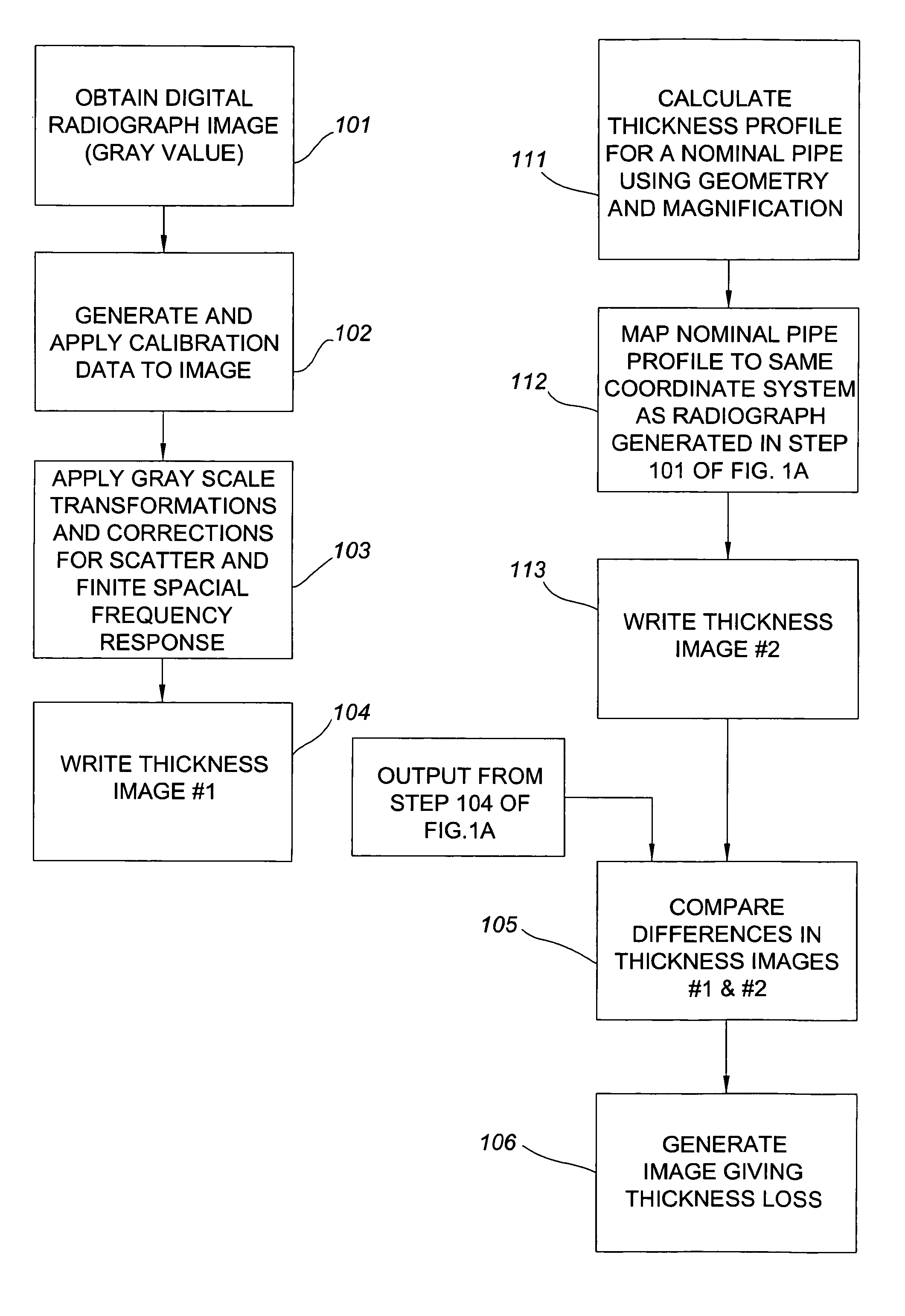
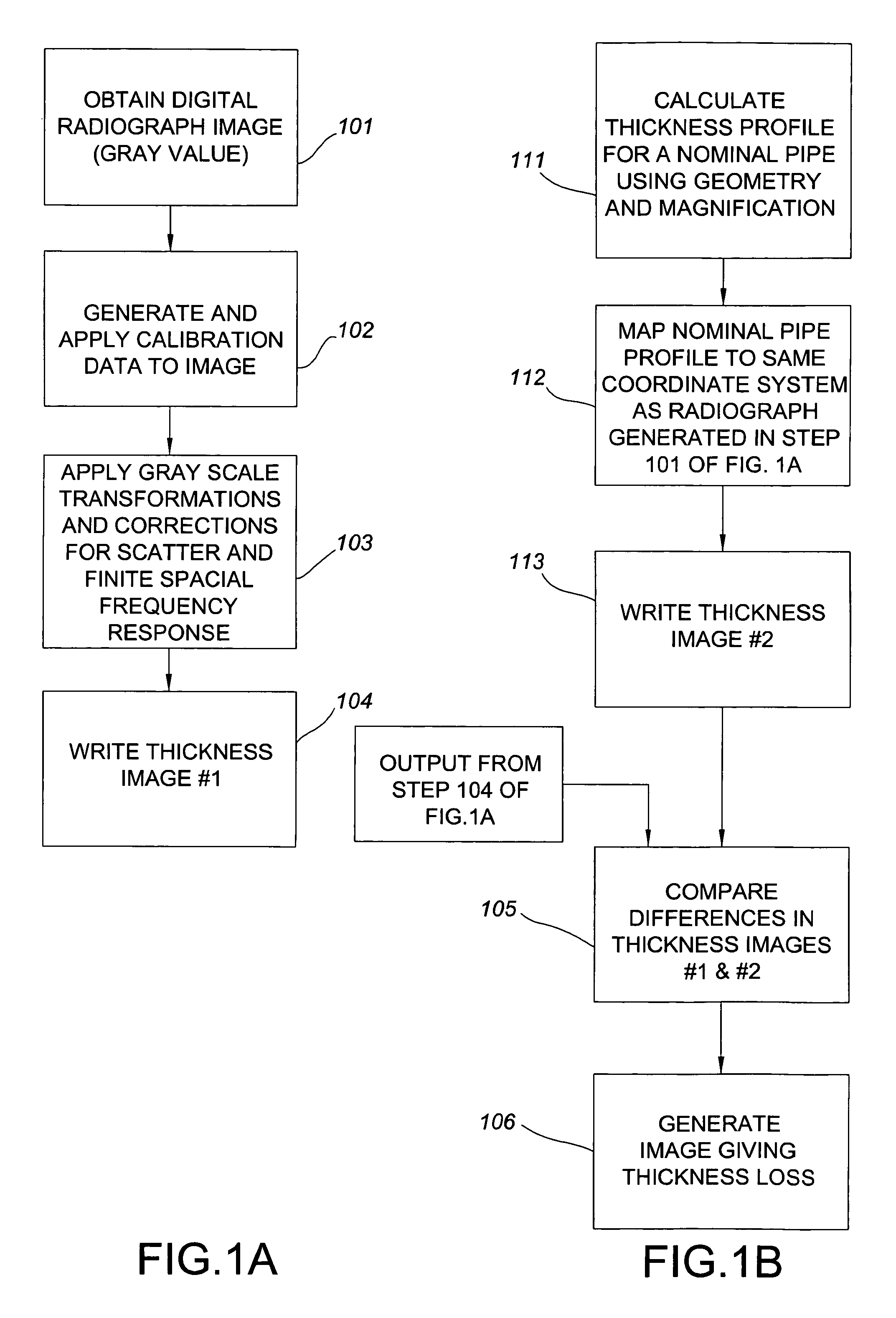
[0032]The motivation for the invention is to utilize radiography for quantitative inspection purposes, rather than its primary use as a qualitative screening tool. Instead of using radiography as a screening tool that serves to identify features or defects, our aim is to use radiography as a primary inspection modality that is capable of estimating wall thicknesses at a level competitive with state of the art ultra-sound technology. If the level of absolute precision in the radiographic measurement is 2-10%, radiography has the potential of yielding more complete information during an inspection because it is an image-based modality which can cover a large area. However, in order to realize the prescribed preci...


PUM


Abstract

A digital radiography imaging system for acquiring digital images of an object, and a method for transforming digital images into an absolute thickness map characterizing the object under inspection. The system includes a radiation source for directing radiation through a desired region of the object, and a radiation detector having a plurality of sensing elements for detecting radiation passing through the object. Numerical data generated from each sensing element is calibrated, for example by correcting for variations in radiation paths between the source and detector, by correcting for variations in the spatial frequency response (MTF) of the detector, by correcting for variations in the geometric profile of the object under inspection, and by correcting for material contained in and / or around the object. The calibrated data is processed in order to generate and display an absolute thickness map of the object. The calibration procedures are adapted for extracting a thickness map from both isotope sources and X-ray tube sources.

Description

CROSS REFERENCE TO RELATED APPLICATION[0001]This application claims the priority benefit of U.S. Provisional Patent Application Ser. No. 60 / 609,934 filed Sep. 15, 2004.FIELD OF THE INVENTION[0002]The present invention relates generally to radiographic imaging systems, and more particularly to methods and algorithms for characterizing the condition of containment vessels and fluid transport piping installations in a quantitative (and qualitative) fashion over large areas. Specifically, the algorithms and methods of the present invention are used to convert a digital measure of a transmitted X-ray spectrum to an absolute measure of material thickness with high accuracy and precision. The imaging system developed in accordance with the present invention is adapted to deliver an X-ray source and detector to a pipe or vessel installation in a well defined geometrical relation, without using the pipework itself as a support structure.BACKGROUND OF THE INVENTION[0003]Most industrial comple...

Claims


Application Information

Patent Timeline
Patent Type & Authority Patents(United States)
IPC IPC(8): G01B15/02
CPCG01B15/025
Inventor LASIUK, BRIAN W.BATZINGER, THOMAS J.VENUGOPAL, MANOHARANDIXON, ELIZABETH L.HOPPLE, MICHAEL R.GOPALIKA, NITYANANDRAMASWAMY, SIVARAMANIVASMISHRA, DEBASISHVENKATACHALAM, RAJASHEKARKOMMAREDDY, VAMISHI KRISHNA REDDY
Owner BL TECH INC
Learn More