Screen system

a screen and basket technology, applied in the direction of screening, moving filter element filtering, screening, etc., can solve the problems of poor sealing between the screen and the basket, easy damage to the screen, and significant downtime of the vibratory screen apparatus, so as to facilitate installation and removal of the screen elements, facilitate the effect of flexible flexibility and convenient formation

Active Publication Date: 2009-01-20
NAT OILWELL VARCO UK
View PDF13 Cites 17 Cited by
  • Summary
  • Abstract
  • Description
  • Claims
  • Application Information

AI Technical Summary

Benefits of technology

[0032]As noted above, the mesh panel may be in the form of a plain mesh, or alternatively in a pre-tensioned form in which a mesh is secured e.g. by means of adhesive or fusing, onto or into an apertured lightweight flexible support plate, or plastic coating thereon etc. The apertured support plate may be of any suitable material including metal, plastics material, or glass or carbon fibre reinforced plastics, although preferably there is used plastics coated metal, especially plastics coated steel. Conveniently the apertured support plate is manufactured by means of punching suitably sized apertures in the support plate, especially using computer controlled punching apparatus. This has the advantage of affording particular flexibility in relation to the production of support plates with various different aperture sizes (whether within the same support plate or in different support plates). Various other techniques well known in the art can also be used for forming the apertures, such as for example, laser cutting. Also in the case of support plates made of plastics materials, especially fibre and / or wire reinforced plastics materials, the apertures are conveniently formed by producing the apertured support plates by means of techniques such as injection moulding.
[0033]With support plates formed of punched metal, it should be noted that the punching process can introduce a degree of bowing into the plate. Given that the mesh is normally attached to the “smooth” side of the punched plate which is also the concave side of the bowed plate, and indeed pretensioned mesh can itself impart a degree of bowing to the plate when it is secured to the support plate, it is then necessary to apply force to the plate so as to reverse the bowing therein, so that it can be mounted onto a support frame with convex further frame elements across which the mesh panel of the screen element is supported. Advantageously therefore such a bowed plate would be subjected to a process such as rolling so as to take out or reverse to a greater or lesser extent any undesirable bowing, prior to securing the suitably tensioned mesh thereto. By avoiding in this way any bowing in the screen elements which differs substantially from that of the support frame further elements, not only is installation and removal of the screen elements facilitated, but also the clamping force is more efficiently utilized.

Problems solved by technology

Hook strip screens have a number of disadvantages including the complex and time consuming mounting of the screen members in the basket, which results in significant downtime of the vibratory screen apparatus and requires the use of multiple parts.
Attaining the correct screen tension for the material to be sieved also involves intricate fine tuning and the screens are easily damaged if too much force is applied when tightening the bolts or loading means to tension the screens.
A further disadvantage is the relatively poor sealing between the screen and basket.
The metal on metal seal often results in leakage with unscreened material passing through gaps between the screen and the basket, and mixing with already screened material below the mesh screen.
Attempts to overcome the poor seal by placing rubber strips or gaskets at the metal / metal interfaces have proved unsatisfactory.
These require intricate and time consuming fitting and frequently work loose during vibration and become lost or lodged in the vibratory machine, obstructing and damaging the machinery.
In addition applying tension to the screen when tightening the tension bolt or loading means gives rise to additional stresses over and above those already suffered by the machine framework due to the vibratory motion, thereby possibly resulting in deterioration of the framework.
Conventional pretensioned screen units with integral support frames have significant disadvantages being bulky, heavy and difficult to handle, transport and store; all very major considerations for use on off shore installations where all of these are at a very high premium.
The design is complex and the frames expensive to construct.
The frames utilise large amounts of material all of which require disposal when the screen units are replaced, which is both inconvenient and expensive and has a negative impact on the environment.
These screen assemblies, however, are very complex in structure with many of the disadvantages and associated expense of conventional pretensioned screens and, in addition, the inconvenience, storage and additional material requirements of the modules.
A further problem that arises with known screen systems is that due to the extra weight of the material being processed which is concentrated, in use of screening apparatus at the back (upstream) end thereof.
The screen mesh in that area is subjected to particularly heavy wear resulting in the frequent need for replacement thereof.
This problem has previously been addressed by using coarser heavy duty mesh in that area, but this inevitably results in reduced screening performance of the screening apparatus.

Method used


Image

  • Screen system
  • Screen system
  • Screen system

Examples


Embodiment Construction

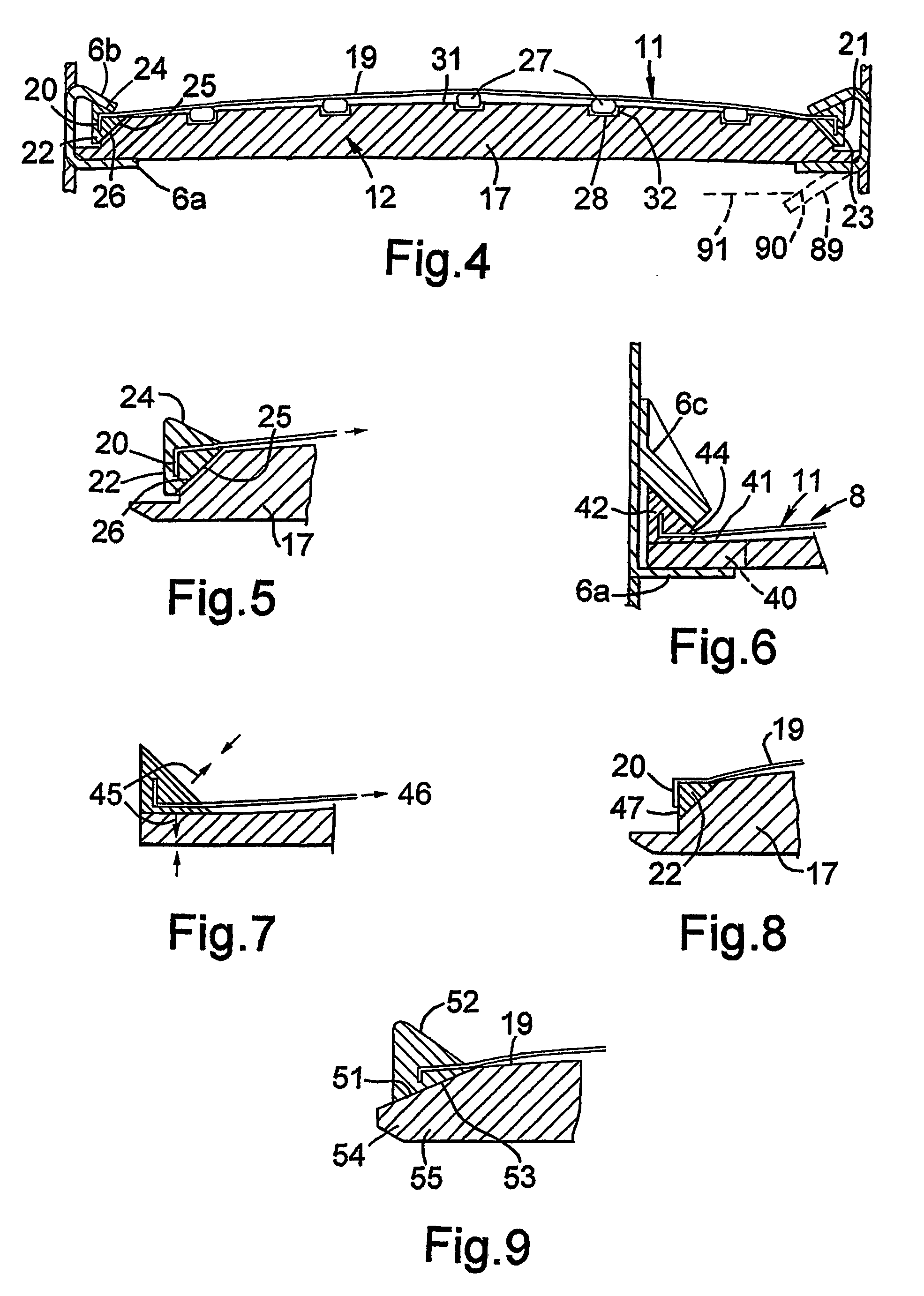
[0054]FIG. 1 shows schematically a vibratory screen apparatus 1 with an outer housing 2 in which is mounted on springs 3 a basket unit 4. Each basket 5 of the basket unit 4 (see also FIG. 2) is generally box shaped with a pair of circumferentially extending inwardly projecting flanges 6 at an intermediate height on the basket walls 7, for supporting a screen system of the invention 8 as typically found in existing pretension screen vibratory machinery. A vibrator unit 9 is secured to the top 10 of the basket unit 4. FIG. 4 shows a screen system 8 comprising a screen element 11 clamped to a support frame 12 (also shown in FIG. 3) between the basket flanges 6.

[0055]The support frame 12 comprises first and second elongate frame elements 13, 14 at opposite end portions 15, 16 and further elongate, third and fourth, frame elements 17, 18 interconnecting them.

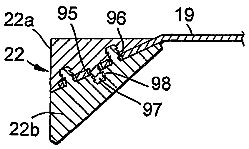
[0056]As shown in FIG. 4 the screen element 11 comprises a mesh panel 19 having cranked opposite end portions 20, 21 anchored in fi...


PUM

PropertyMeasurementUnit
aperture diametersaaaaaaaaaa
angleaaaaaaaaaa
tensionsaaaaaaaaaa

Abstract

A screen system 8 suitable for use in a vibratory screen apparatus 1, comprising: a screen element 11 consisting essentially of a mesh panel 19 provided with first and second elongate support members 22, 23 extending along opposite end portions 20, 21; and a support frame 12 therefore. The support frame 12 has spaced apart first and second elongate frame elements 13, 14 for engagement with said screen element support members 22, 23 and further elongate frame elements 17, 18 extending between the first and second frame elements 13, 14 for supporting the mesh panel 19. The support frame 12 is provided with at least one mesh panel support 27 provided with an elevating support surface, which tensions the screen element 11 across the support surface 27 and between the screen element support members 22, 23. The latter 22, 23 and the first and second frame elements 13, 14 are being formed and arranged for secure interengagement. At least one of the screen element support members 22, 23 and the respective one of the first and second frame elements 13, 14 is formed and arranged so that when the screen element 19 is tensioned by the mesh panel support 27 with the support surface thereof elevated, the mesh panel 19 is securely held under tension and the screen element support members 22, 23 are driven into securely gripped interengagement with the frame elements 13, 14.

Description

FIELD OF THE INVENTION[0001]The present invention relates to screen systems for use in vibratory screen apparatus suitable for use in liquid solid separation and classification including inter alia, the sifting of drilling mud, cuttings and like material derived from oil-well drilling.BACKGROUND OF THE INVENTION[0002]Conventional vibratory apparatus for sifting mud and like material in the oil industry generally utilise screens of either hook strip or pretensioned design. Hook strip screens generally consist of single or multiple layers of mesh bonded together, which are tensioned after mounting in the basket of the vibratory screen apparatus. Two opposed ends of the screen are fitted with a turn back element to form a hook strip which is hooked around a tension rail, the latter being attached to the side wall of the basket, typically via a tension bolt, though other loading means to apply tensioning and securing forces may be employed. Tightening the tension bolt moves the tension ...

Claims


Application Information

Patent Timeline
Patent Type & Authority Patents(United States)
IPC IPC(8): B07B1/49B01D33/03B07B1/48
CPCB01D33/0376B07B1/485
Inventor FISHER, GEORGE WILLOXBAILEY, MARSHALL GRAHAM
Owner NAT OILWELL VARCO UK
Why Eureka
Try Eureka