
Apparatus and method to support pipelining of differing-latency instructions in a multithreaded processor

a multi-threaded processor and instruction technology, applied in the field of processors, can solve the problems of reducing the usable die per wafer, affecting the performance of the instruction, so as to prevent the issue of shorter-latency instruction

Active Publication Date: 2009-01-13
ORACLE INT CORP
View PDF55 Cites 97 Cited by
  • Summary
  • Abstract
  • Description
  • Claims
  • Application Information

AI Technical Summary

Benefits of technology

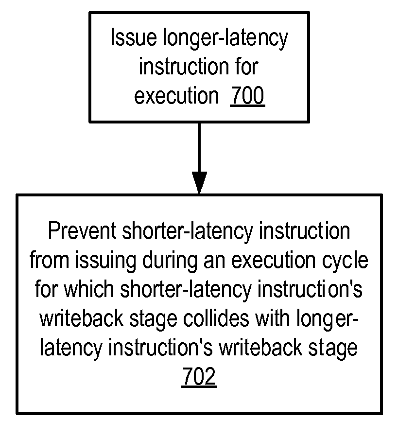
[0007]Various embodiments of an apparatus and method to support pipelining of variable-latency instructions in a multithreaded processor are disclosed. In one embodiment, a processor may include instruction fetch logic configured to issue a first instruction from one of a plurality of threads during one execution cycle and to issue a second instruction from another one of the plurality of threads during a successive execution cycle. The processor may also include a first execution unit configured to execute a shorter-latency instruction and to write a result of the shorter-latency instruction to a result write port during a first writeback stage that occurs a first number of execution cycles after issue of the shorter-latency instruction, and a second execution unit configured to execute a longer-latency instruction and to write a result of the longer-latency instruction to the result write port during a second writeback stage that occurs a second number of execution cycles after issue of the longer-latency instruction, where the second number is greater than the first number. The instruction fetch logic may be further configured to guarantee access by the second execution unit to the result write port during the second writeback stage by preventing issue to the first execution unit of the shorter-latency instruction during an execution cycle for which the first writeback stage collides with the second writeback stage.
[0008]A method is further contemplated that in one embodiment may include issuing a first instruction from one of a plurality of threads during one execution cycle, issuing a second instruction from another one of the plurality of threads during a successive execution cycle, writing a result of a shorter-latency instruction to a result write port during a first writeback stage that occurs a first number of execution cycles after issuing the shorter-latency instruction, and writing a result of a longer-latency instruction to the result write port during a second writeback stage that occurs a second number of execution cycles after issuing the longer-latency instruction, where the second number is greater than the first number. The method may further include preventing issue of the shorter-latency instruction during an execution cycle for which the first writeback stage collides with the second writeback stage.

Problems solved by technology

Providing a dedicated write port for each instruction of differing latency may be expensive in terms of design effort, manufacturing cost, and processor performance, as additional write ports typically require increased processor die area, which may in turn reduce usable die per wafer and lengthen critical circuits.
Further, if a write conflict between differing-latency instructions is relatively rare, dedicated write ports may be poorly utilized.
On the other hand, requiring differing-latency instructions to arbitrate for a write port may also increase design complexity and impact performance.
For example, if a given instruction loses arbitration and cannot write back during a given execution cycle, its result may need to be queued for another arbitration attempt, or execution may stall until writeback can proceed.
Additionally, if an arbitration algorithm is not designed and verified to be fair, performance of certain types of instructions could suffer.
In the worst case, a livelock or deadlock condition could arise if a given instruction is queued or stalled indefinitely while waiting for writeback.

Method used


Image

  • Apparatus and method to support pipelining of differing-latency instructions in a multithreaded processor
  • Apparatus and method to support pipelining of differing-latency instructions in a multithreaded processor
  • Apparatus and method to support pipelining of differing-latency instructions in a multithreaded processor

Examples


Embodiment Construction

Overview of Multithreaded Processor Architecture

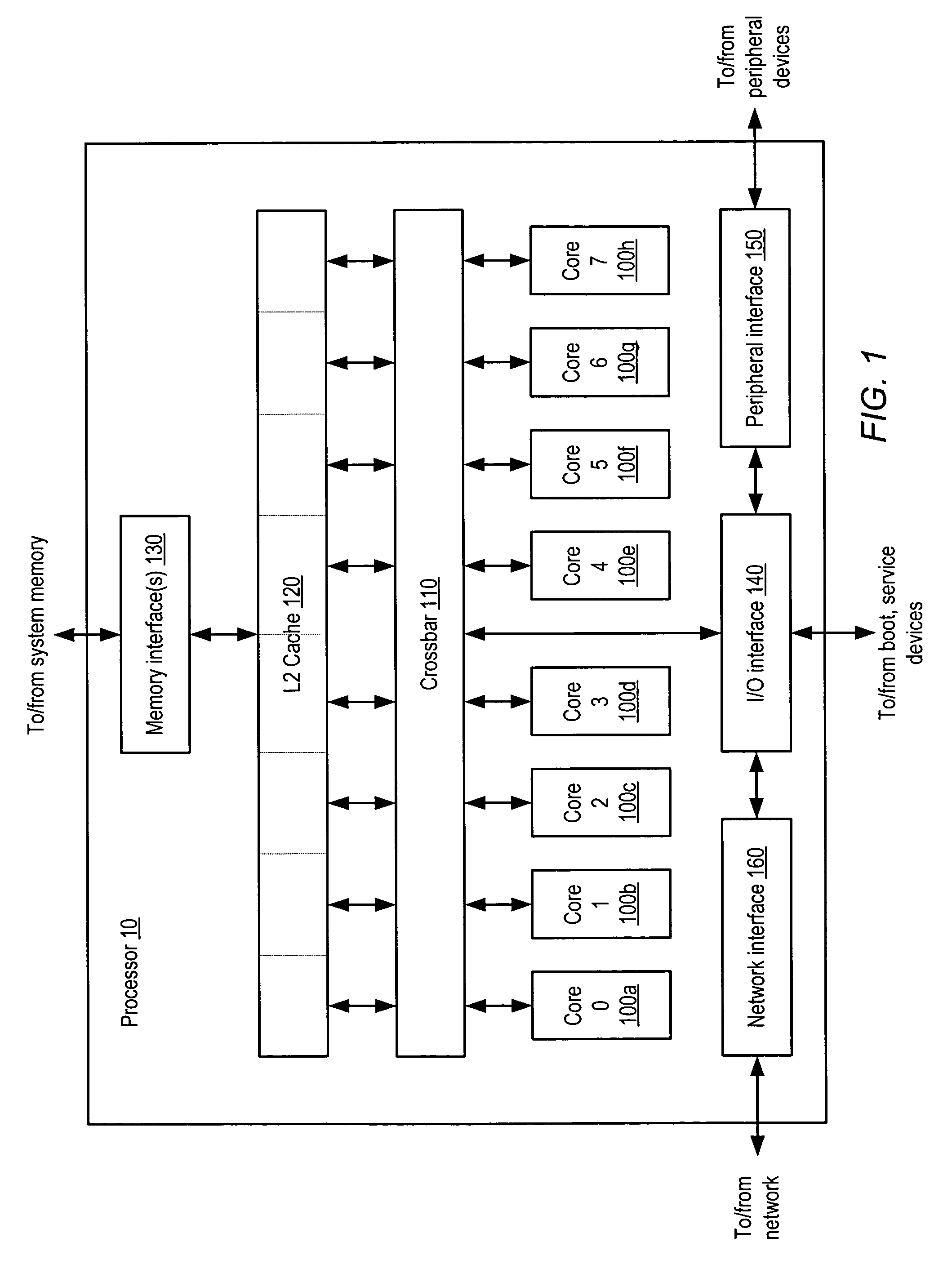
[0019]A block diagram illustrating one embodiment of a multithreaded processor 10 is shown in FIG. 1. In the illustrated embodiment, processor 10 includes a plurality of processor cores 100a-h, which are also designated “core 0” though “core 7”. Each of cores 100 is coupled to an L2 cache 120 via a crossbar 110. L2 cache 120 is coupled to one or more memory interface(s) 130, which are coupled in turn to one or more banks of system memory (not shown). Additionally, crossbar 110 couples cores 100 to input / output (I / O) interface 140, which is in turn coupled to a peripheral interface 150 and a network interface 160. As described in greater detail below, I / O interface 140, peripheral interface 150 and network interface 160 may respectively couple processor 10 to boot and / or service devices, peripheral devices, and a network.

[0020]Cores 100 may be configured to execute instructions and to process data according to a particular instruction s...


PUM


Abstract

An apparatus and method to support pipelining of variable-latency instructions in a multithreaded processor. In one embodiment, a processor may include instruction fetch logic configured to issue a first and a second instruction from different ones of a plurality of threads during successive cycles. The processor may also include first and second execution units respectively configured to execute shorter-latency and longer-latency instructions and to respectively write shorter-latency or longer-latency instruction results to a result write port during a first or second writeback stage. The first writeback stage may occur a fewer number of cycles after instruction issue than the second writeback stage. The instruction fetch logic may be further configured to guarantee result write port access by the second execution unit during the second writeback stage by preventing the shorter-latency instruction from issuing during a cycle for which the first writeback stage collides with the second writeback stage.

Description

BACKGROUND OF THE INVENTION[0001]1. Field of the Invention[0002]This invention relates to processors and, more particularly, to scheduling and coordination of instruction execution within a processor.[0003]2. Description of the Related Art[0004]In some pipelined processor embodiments implementing a given instruction set architecture (ISA), different instructions may be configured to execute with different latencies according to their relative complexity. For example, multiplication instructions may execute in a greater number of execution cycles than add instructions. In some such embodiments, two instructions that begin execution in two different execution cycles may complete execution and produce a result to be written back (for example, to a register file) during the same execution cycle.[0005]Providing a dedicated write port for each instruction of differing latency may be expensive in terms of design effort, manufacturing cost, and processor performance, as additional write por...

Claims


Application Information

Patent Timeline
IPC IPC(8): G06F9/30
CPCG06F9/3836G06F9/3851G06F9/3857G06F9/3877G06F9/3873G06F9/3858
Inventor BROOKS, JEFFREY S.OLSON, CHRISTOPHER H.GOLLA, ROBERT T.
Owner ORACLE INT CORP
Learn More