
Method for manufacturing windmill blades

Active Publication Date: 2009-01-06
SIEMENS GAMESA RENEWABLE ENERGY AS
View PDF28 Cites 45 Cited by
  • Summary
  • Abstract
  • Description
  • Claims
  • Application Information

AI Technical Summary

Benefits of technology

[0014]By making the blade in one piece, where a substantial part of the outer side is an impression of one or more outer mold parts there is achieved the advantage that by using gelcoat in the mold or by a subsequent simple surface, the blade surface may appear in the quality required with regard to aerodynamic efficiency and aesthetic impression.
[0016]By making the blade in one piece in a closed process, the workers' exposure to possible environmentally hazardous substances in the composite material is eliminated, so that the need for personal protective means may be reduced to an absolute minimum.
[0017]By making the blade in a sandwich construction with a core material which largely runs continuously around the cross-sectional profile of the blade, there is achieved a particularly advantageous combination of production technique and properties of the finished product. The core material may thus be used as evacuation and flow duct by a vacuum based process, and the continuous process ensures uniform cross-sectional properties without disadvantageous transitions between sandwich and solid structure in highly loaded areas. The continuous core material and the real separation of the load bearing part of the laminate in an outer and an inner section furthermore provides the constructional advantage that a possible crack formation in one (outer or inner) laminate only implies a very small risk of propagation to the other laminate. Hereby is achieved a hitherto unknown redundancy of the structure.

Problems solved by technology

Such methods by winding have the disadvantage that after setting, the winded item will normally appear with the raw composite material surface as an external surface which is incompatible with many applications, e.g. for windmill blades.
Another drawback by this method is that the winding normally presupposes use of a mandrel with a certain strength which therefore is desired to be reused.
Such a method may thus not be used for e.g. tanks or whole windmill blades.
However, it is a problem with this method that it may be difficult to ensure a satisfying quality of the glue joints established in the interior of the structure for the mutual joining of the half-shells and for joining possible beams with the half-shells.
This is partly due to fundamental problems regarding material technology, partly to more specific manufacturing problems.
The fundamental problems regarding material technology may summarizingly be described as consequences of the impossibility of having the same material properties in the glue as in the rest of the blade.
To this comes that glue materials are often brittle and may therefore be vulnerable to local moments tending to open the glue joint, so-called peeling.
Such local moments will particularly occur by very large loads on the blade, where non-linear effects may imply the blade cross-section changing its shape.
By virtue of glue materials normally having relatively brittle properties, there may be the subsequent danger that cracks in glue joints propagate far beyond the area in which the original overloads have occurred.
Among the manufacturing problems, one of the essential is that the glue joints are provided at leading and trailing edge and between beam and shell, so that a glue joint is established on the unprepared surface at the inner side of the shell laminate.
The problem of this joint is that the glue surface may only be defined within a certain large range of tolerance.
This reduction may not always be provided with the necessary tolerances why a real adaptation will require working of the assembly faces, which in turn will imply a large rise in the costs.
Another problem is that the deformations arising in the blade shells in connection with small variations in the manufacturing process can give a varying gap inside the cavity of the item so that it may be difficult to ensure a complete filling of glue of the interspace between beam and shell.
All these problems with tolerances have the result that glue joints generally may have varying cross-sections and fillings which in turn implies a risk of considerable stress concentrations in the glue and the adjoining blade shells and beams.
Furthermore, it is a problem that most glue materials presupposes that the surfaces to be bonded are ground in advance with the associated problems of maintaining the necessary tolerances.
Finally, the glue joints are usually difficult to inspect visually as well as they are difficult to inspect by NDT methods (non-destructive testing) due to the tapering laminate and the irregular geometry of the item.
It is also a problem with methods based on bonding individual parts of blades that even though individual sections of the blades may be produced in closed processes with small or no environmental loads, this is usually not the case with the bonding itself.
Here, workers will usually be exposed to grind dust from dry grinding, partly because it is unfavorable to the subsequent gluing process to perform wet grinding and partly because they are exposed to contact with and / or vapors from the glue material itself, implying need for personal protective means.

Method used


Image

  • Method for manufacturing windmill blades
  • Method for manufacturing windmill blades
  • Method for manufacturing windmill blades

Examples


Embodiment Construction

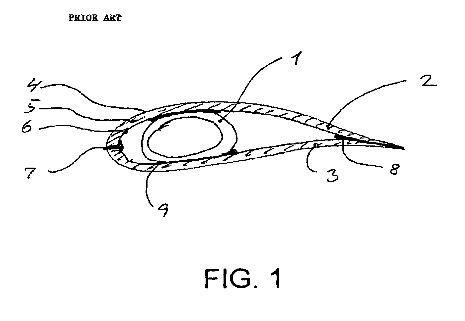
[0019]FIG. 1 shows a windmill blade made according to a usual method. A beam 1 is made by winding around a mandrel which later is taken out of the beam. Around the beam is glued two half-shells 2 and 3. Each half-shell consists of an outer laminate 4, a sandwich core 5, which e.g. can be made in balsa wood or PVC foam, and an inner laminate 6. The half-shells are fastened by glue joints at the leading edge 7, at the trailing edge 8, and against the beam 9. A blade made according to this usual method initially has three main parts, namely the beam 1 and the two half-shells 2 and 3. According to the circumstances, these main parts may be supplemented with further main parts, e.g. at the root of the blade, for forming transition to pitch bearing and / or rotor hub.

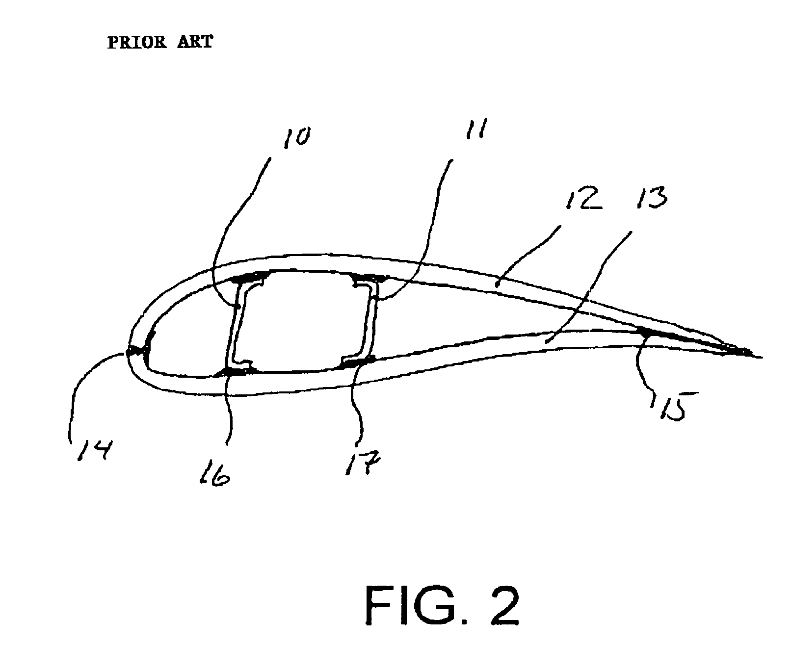
[0020]FIG. 2 shows a windmill blade made according to another usual method. Two beams 10 and 11 are made by molding in separate molds. The two beams are joined with two half-shells 12 and 13. The half-shells are fastened by glu...


PUM

PropertyMeasurementUnit
Angleaaaaaaaaaa
Temperatureaaaaaaaaaa
Pressureaaaaaaaaaa

Abstract

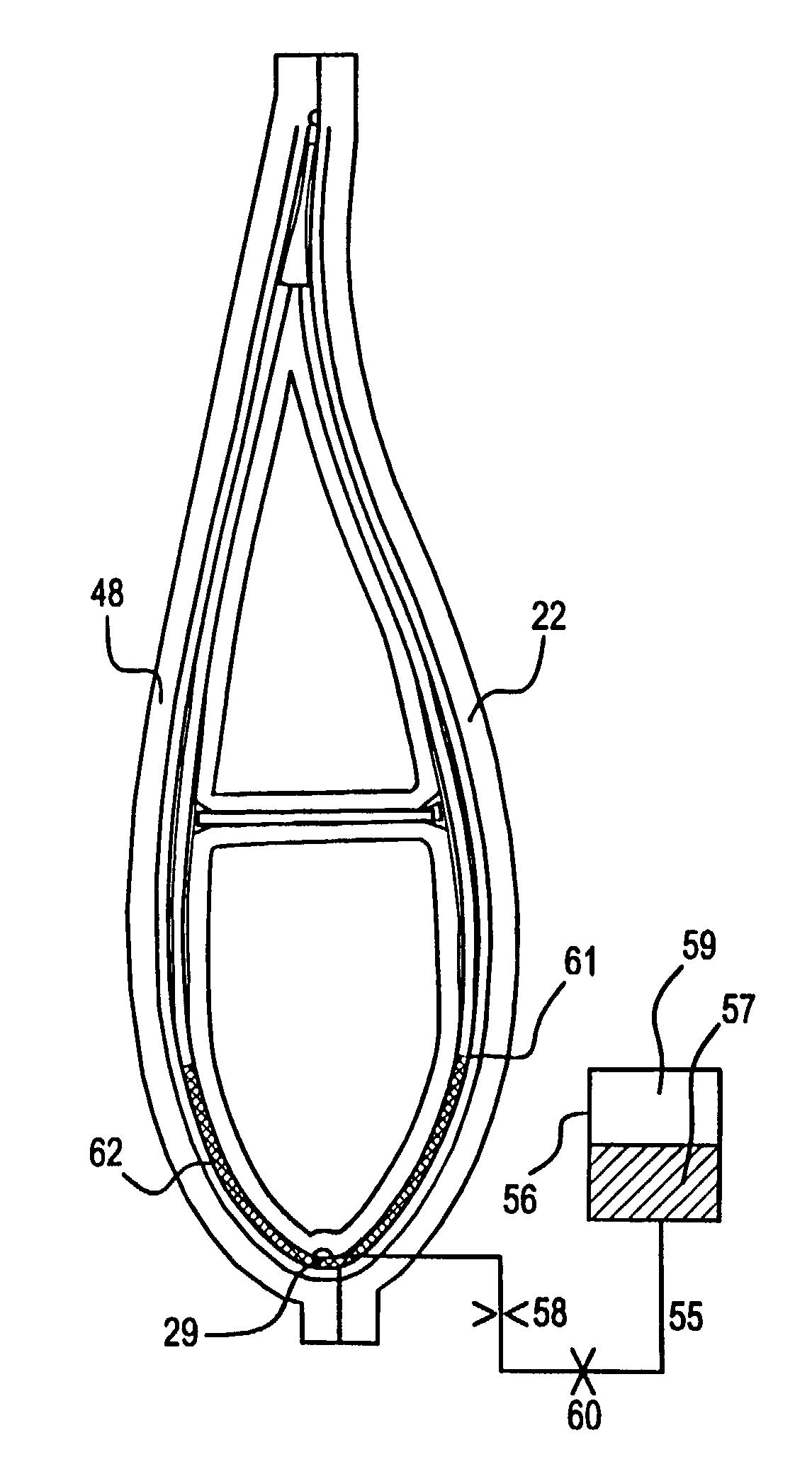
A method for making a windmill blade is provided, whereby problems with glue joints and with exposure of the workers to environmentally hazardous substances are avoided. This is effected by making the windmill blade in a closed mold with a mold core (3) inside mold parts (22, 48) for formation of a mold cavity (51), in which fiber material (45, 47) and core material (46) are placed. After applying vacuum to the mold cavity (51), matrix material (57) is injected via a filling pipe (29), which is placed at a downwardly oriented side edge of the blade during the filling. Hereby is established a flow front (61) which is used for indicating complete filling when this reaches the trailing edge of the blade and penetrates out through overflow apertures.

Description

FIELD OF THE INVENTION[0001]The present invention concerns a method for making windmill blades of composite materials such as glass or carbon fiber reinforced epoxy, polyester, vinyl ester, or thermoplastic.BACKGROUND ART[0002]Different methods for making windmill blades are known.[0003]Thus it is known that windmill blades may be made by winding roving tapes or roving bundles around a core or mandrel. Methods for this are inter alia described in U.S. Pat. Nos. 4,242,160 and 4,381,960.[0004]Such methods by winding have the disadvantage that after setting, the winded item will normally appear with the raw composite material surface as an external surface which is incompatible with many applications, e.g. for windmill blades. A satisfactory surface quality therefore presupposes a finishing treatment, e.g. by the bonding of shells made separately.[0005]Another drawback by this method is that the winding normally presupposes use of a mandrel with a certain strength which therefore is de...

Claims


Application Information

Patent Timeline
IPC IPC(8): B29C70/36B29C70/48B29C33/00B29D99/00B29C70/44B29C70/54F03D1/06
CPCB29C70/443B29C70/48B29C70/546F03D1/0675B29D99/0028Y02T50/433Y02E10/721Y02E10/72Y02P70/50Y02T50/40
Inventor STIESDAL, HENRIKENEVOLDSEN, PEDER BAYJOHANSEN, KAJKRISTENSEN, JENS JORGEN ONORLEM, MICHAELWINTHER-JENSEN, MARTIN
Owner SIEMENS GAMESA RENEWABLE ENERGY AS
Learn More