Period indicator

a technology of period indicators and indicators, applied in the field of period indicators, can solve the problems of increasing costs, complicated production steps, and imposing limitations on the letters or marks to be used for display, and achieve the effect of improving display performan

Inactive Publication Date: 2009-01-06
NIPPON PAPER PAPYLIA +1
View PDF30 Cites 3 Cited by
  • Summary
  • Abstract
  • Description
  • Claims
  • Application Information

AI Technical Summary

Benefits of technology

[0008]The present invention contemplates to provide a period indicator which meets the above-mentioned trend calling for diversified display modes, and specifically, the invention provides a period indicator including an indicative section which is formed from a single component material so as to be able to attain a stepwise display through a simple process, thereby leading to an improved display performance.
[0009]The present invention has been accomplished on the basis of the following inventors' finding. When a liquid is contained in a liquid permeable indicative substrate on which a liquid permeable indicative section having a low light refractive index is partially overlaid, the indicative section is rendered transparent and thus invisible. After that, when the liquid is allowed to volatilize to thereby reduce the amount of the remaining liquid, indicative signs can be observed more easily in portions bearing larger amounts of coating per unit area of the indicative section and thus presenting a higher elevation from the surface of the substrate, as a result of accelerated speed of becoming opaque.
[0020]When the amount of coating per unit area is increased, the height of the indicative section as measured from the substrate surface becomes high. The present inventors have found that development of a sign occurs quicker with increasing amount of coating applied per unit area of indicative section and with increasing height of the indicative section as measured from the substrate surface. That is, in the case where two indicators have substrates of the same size, and are identical in terms of the position of the indicative section disposed on the substrate and the shape of the indicative section, a difference in the coating amount per unit area of the indicative section—i.e., a difference in the height as measured from the substrate surface—results in development of a sign with a time lag. Specifically, the greater the height from the substrate surface, the earlier the moment of development of a sign.
[0026]Even when respective indicative regions have the same coating amount per unit area, if the regions have different sizes, the moment at which a sign is developed is affected; i.e., in the case of a larger coated area and a wider coated portion, sign development tends to occur from the periphery of the coated portion. Therefore, combination of “difference in coating amount per unit area” and “difference in the area of coated portion” can attain more clear stepwise indication. That is, the interval between points in time involved in the stepwise indication can be prolonged by allotting a larger coating amount and a larger coating area to the region intended to develop a sign earlier, and at the same time, allotting a smaller coating amount and a narrow region width to the region intended to develop a sign later.
[0030]Also, the indicative section of the period indicator of the present invention is designed such that, in accordance with the decrease in amount of the remaining liquid, an indication emerges sequentially from the region having the largest amount of coating, and when the region having the smallest amount of coating has come to present an indication, the indicative section as a whole completes its showing of indication. In other words, the indicative section can be designed such that the respective regions sequentially develop signs starting from the region of the earliest indication, and when the region of the slowest indication has developed its indication, the entire indicative section conveys a certain message. This mode is beneficial in that the user of the period indicator can received better warning.
[0031]All the regions of the indicative section of the period indicator of the present invention can be formed by use of a single coating solution. Only repeating a simple process of printing or coating can provide regions of highly indicative effect.

Problems solved by technology

In either case, limitations are imposed on the letters or marks to be used for display.
As many functions for attaining diversified modes of display have been added, there have arisen needs for modification of the composition of the material that forms the indicative section, making production steps intricate and increasing costs.

Method used


Image

  • Period indicator
  • Period indicator
  • Period indicator

Examples


example 1

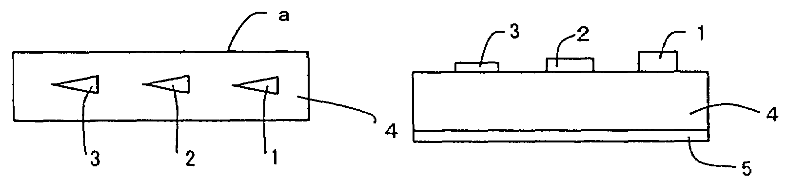
[0098]An indicative substrate “a” as shown in FIGS. 1 and 2 was prepared in the following manner.

[0099]A polypropylene film (covering 5) was overlaid on the surface of one side of a blue wet-laid nonwoven fabric, thereby forming a substrate 4. On the substrate 4, an indicative section containing three aligned, isosceles triangular regions 1, 2, and 3 was formed through screen printing by use of a material containing amorphous silica. The amounts of coating per unit surface area of the regions 1, 2, and 3 of the indicative section were adjusted to three different levels: 120 g / m2, 55 g / m2, and 35 g / m2, respectively. The regions of the indicative section differ in whiteness from one another due to a difference in masking performance caused by different amounts of coating. To the thus-formed indicative substrate “a,” oily liquid was incorporated, whereby a period indicator A was prepared.

[0100]The above materials and methods are described in more detail below.[0101]Substrate: Blue wet-...

example 2

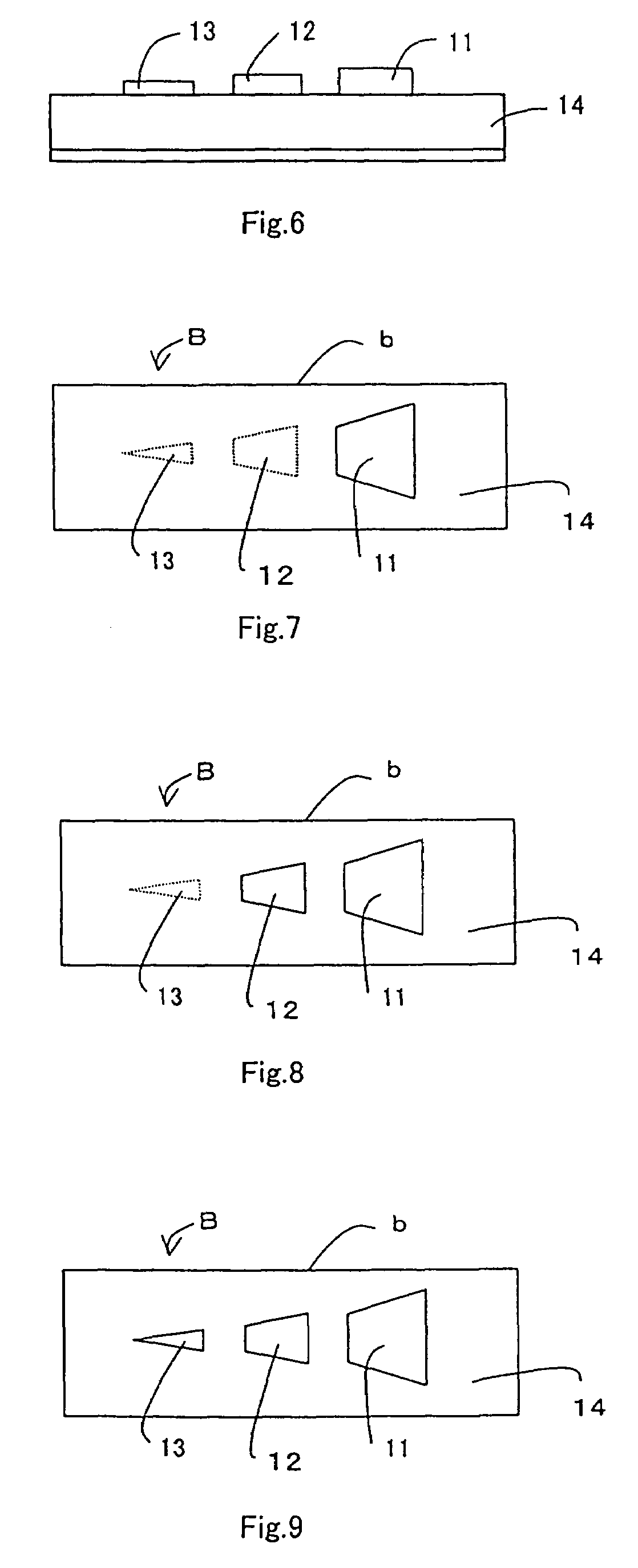
[0107]An indicative substrate “b” as shown in FIG. 6 was prepared in the following manner.

[0108]Through use of a material similar to that employed in Example 1, an indicative section consisting of regions 11, 12, and 13 was formed on the substrate surface through screen printing. The three regions forming in combination an isosceles triangle were discretely disposed with spaces between the regions. The coating amounts of the indicative-section-forming material applied to the regions were different from one another. The area proportions of the regions 11, 12, and 13 of the indicative section were 4.7:2.9:1. The amounts of coating per unit surface area of the regions 11, 12, and 13 were 82 g / m2, 60 g / m2, and 24 g / m2, respectively. Similar to the case of Example 1, dimethyl phthalate was incorporated into the thus-formed indicative substrate “b”, whereby a period indicator B was prepared.

[0109]The above period indicator B was left to stand at room temperature (23° C.) under calm condit...

example 3

[0111]An indicative substrate “c” as shown in FIG. 10 was prepared in the following manner.

[0112]Through use of a material similar to that employed in Example 1, an indicative section consisting of regions 21, 22, and 23 was formed on the substrate surface through screen printing. The three regions forming in combination an isosceles triangle were disposed in contact with one another. The coating amounts of indicative-section-forming material applied to the regions were different from one another. The area proportions of the regions 21, 22, and 23 of the indicative section were 4.7:2.9:1. The amounts of coating per unit surface area of the regions 21, 22, and 23 were 68 g / m2, 35 g / m2, and 18 g / m2, respectively. Similar to the case of Example 1, dimethyl phthalate was incorporated into the thus-formed indicative substrate “c”, whereby a period indicator C was prepared.

[0113]In order to accelerate changes in development of a sign, the above period indicator C was left to stand under t...


PUM

PropertyMeasurementUnit
densityaaaaaaaaaa
densityaaaaaaaaaa
densityaaaaaaaaaa

Abstract

A period indicator including a liquid-permeable substrate and an indicative section which is overlaid on a portion of the substrate and which is formed from a liquid-permeable material having a low light refractive index, the indicator containing a volatile liquid, wherein the indicative section is formed by coating a surface of the substrate with an indicative-section-forming material prepared by mixing a binder and finely divided particulate matter having a low light refractive index, the indicative section is composed of two or more regions, and the regions differ in height from one another as measured from the surface of the substrate, as the coating amounts per unit area of the indicative section forming material in respective regions differ from one another. Since the period indicator can indicate the chemical-containing state stepwise, it is useful for indicating the available period of use of a chemical such as a mothproofing agent, an insecticide, a deodorant, or a fragrance.

Description

TECHNICAL FIELD[0001]The present invention relates to a period indicator with which users can determine the effective period; i.e., the time remaining until expiration, of a liquid chemical or a similar substance. More particularly, the invention relates to a period indicator capable of showing the quantity of the remaining liquid, such as a liquid chemical, in a stepwise manner until the liquid arrives at the endpoint of its effective period.BACKGROUND ART[0002]Hitherto, in order to warn users of mothproofing agents, insecticides, deodorants, fragrance, and similar products that the term of efficacy of such chemicals is about to expire, there have been proposed various types of period indicators which display the quantity-related status of the liquid chemical.[0003]For example, Japanese Patent Publication (kokoku) No. SHO 63-24961 or Japanese Utility Model Publication (kokoku) No. HEI 5-938 discloses a sheet structure having an indicative section and impregnated with a liquid chemi...

Claims


Application Information

Patent Timeline
Patent Type & Authority Patents(United States)
IPC IPC(8): G04F1/02G01K3/04G04F1/06
CPCG01K3/04G04F1/02G04F1/06G09F3/02
Inventor MOCHIZUKI, YOSHIHIDEISHINO, YOSHIAKIKANOMATA, YOSHITERUSATO, MAKOTO
Owner NIPPON PAPER PAPYLIA
Why Eureka
Try Eureka