
Electrical load control device

a technology of load control device and electric load, which is applied in the direction of electric devices, battery/fuel cell control arrangements, electric devices, etc., can solve the problems of electrical load power supply stoppage and driver's discomfor

Inactive Publication Date: 2008-12-23
TOYOTA JIDOSHA KK
View PDF10 Cites 29 Cited by
  • Summary
  • Abstract
  • Description
  • Claims
  • Application Information

AI Technical Summary

Benefits of technology

The present invention provides an electrical load control device that can supply power to multiple electrical loads without causing a problem when shutting off the power supply to one of the loads. The device detects a power shut-off demand to one of the loads and sends a warning signal to another load that it is in a power shut-off permitting state. The load control device then controls a relay to bring the energy storage mechanism and the electrical loads into a shut-off state. This prevents unstable behavior of the traction motor or other malfunctions in the running system caused by sudden shut-off of the power supply. The device can also detect the malfunction and transmit the information indicating the load is in a power shut-off permitting state to the control device, which will bring the relay to the shut-off state to prevent the problem in the first electrical load. The energy storage mechanism is preferably a secondary battery.

Problems solved by technology

Thus, the shutting off the system main relay causes the stop of the power supply to the electrical load.
In such a case, a driver feels uncomfortable.

Method used


Image

  • Electrical load control device
  • Electrical load control device
  • Electrical load control device

Examples


Embodiment Construction

[0026]An embodiment of the present invention will be hereinafter described with reference to the drawings. In the following description, the same reference numerals are given to the same parts and these names and functions are also the same. Accordingly, the detailed description thereof will not be repeated.

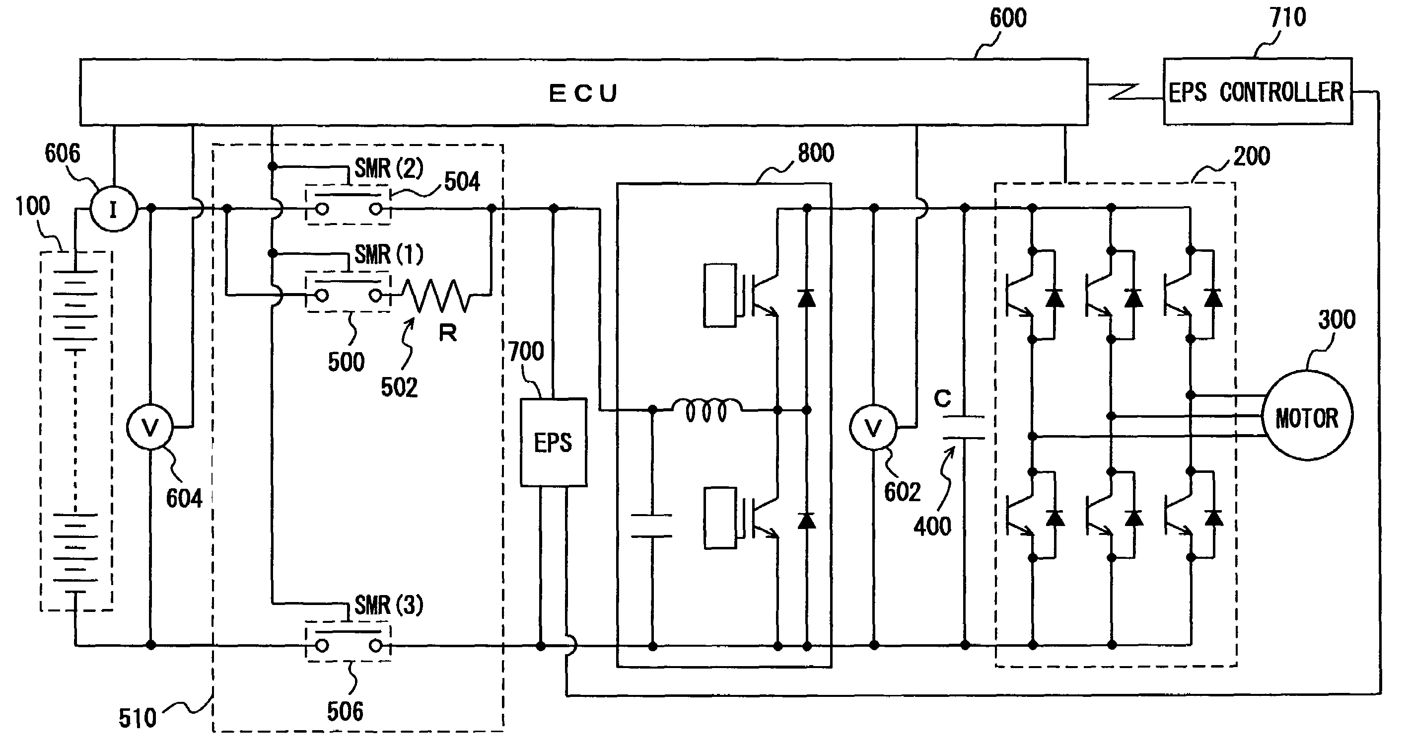
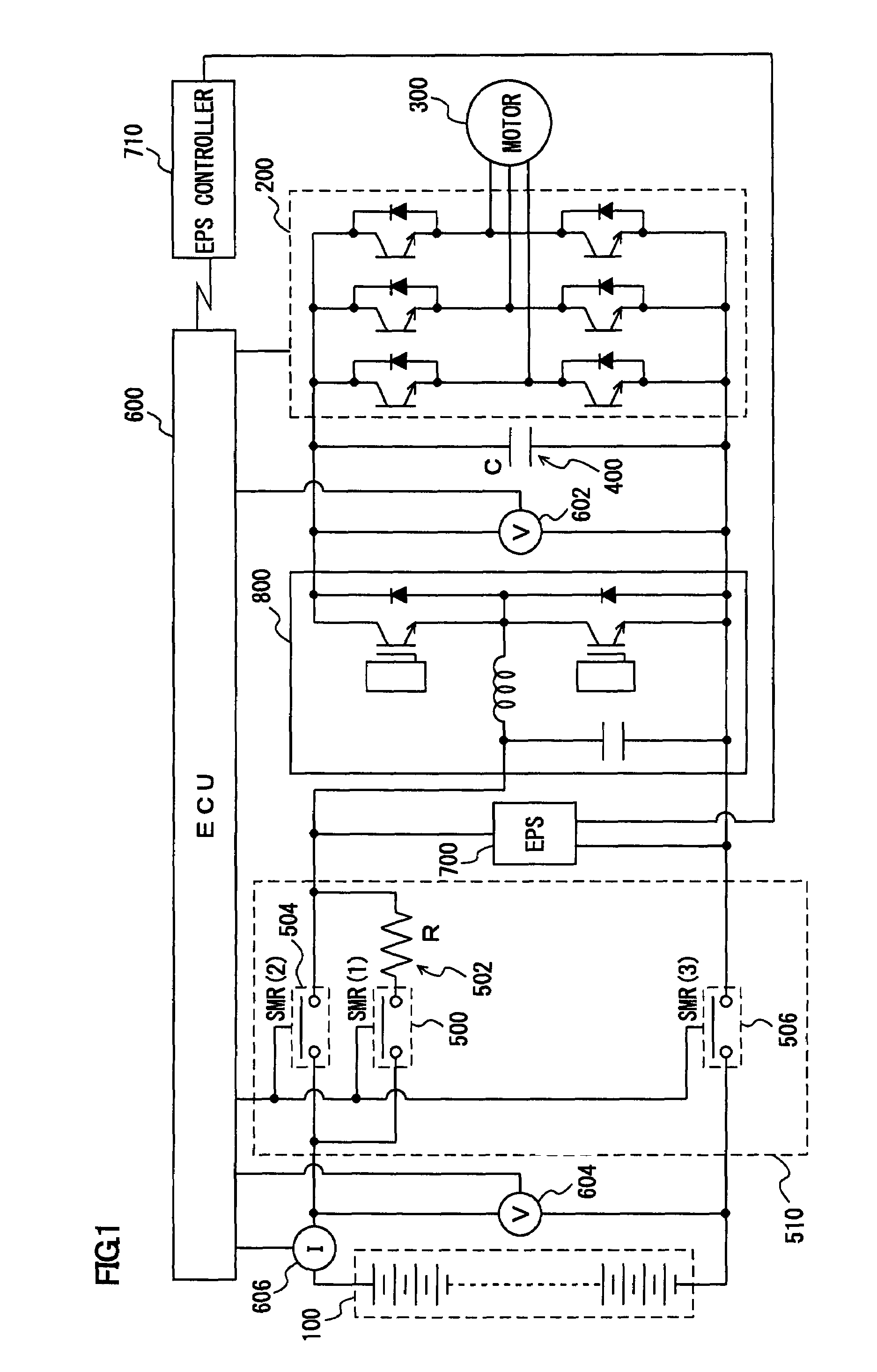
[0027]With reference to FIG. 1, a description will be given of a vehicle mounted with a control device according to an embodiment of the present invention. This vehicle includes a battery 100, an inverter 200, a traction motor 300, a condenser 400, a system main relay 510 (SMR (1) 500, limiting resistor 502, SMR (2) 504, SMR (3) 506), and an ECU (Electronic Control Unit) 600. The control device according to the embodiment is realized by a program preformed by ECU 600. In this embodiment, the description is given of the vehicle that is an electric vehicle running only by a driving force from traction motor 300. However, the vehicle mounted with the electrical load control device a...


PUM


Abstract

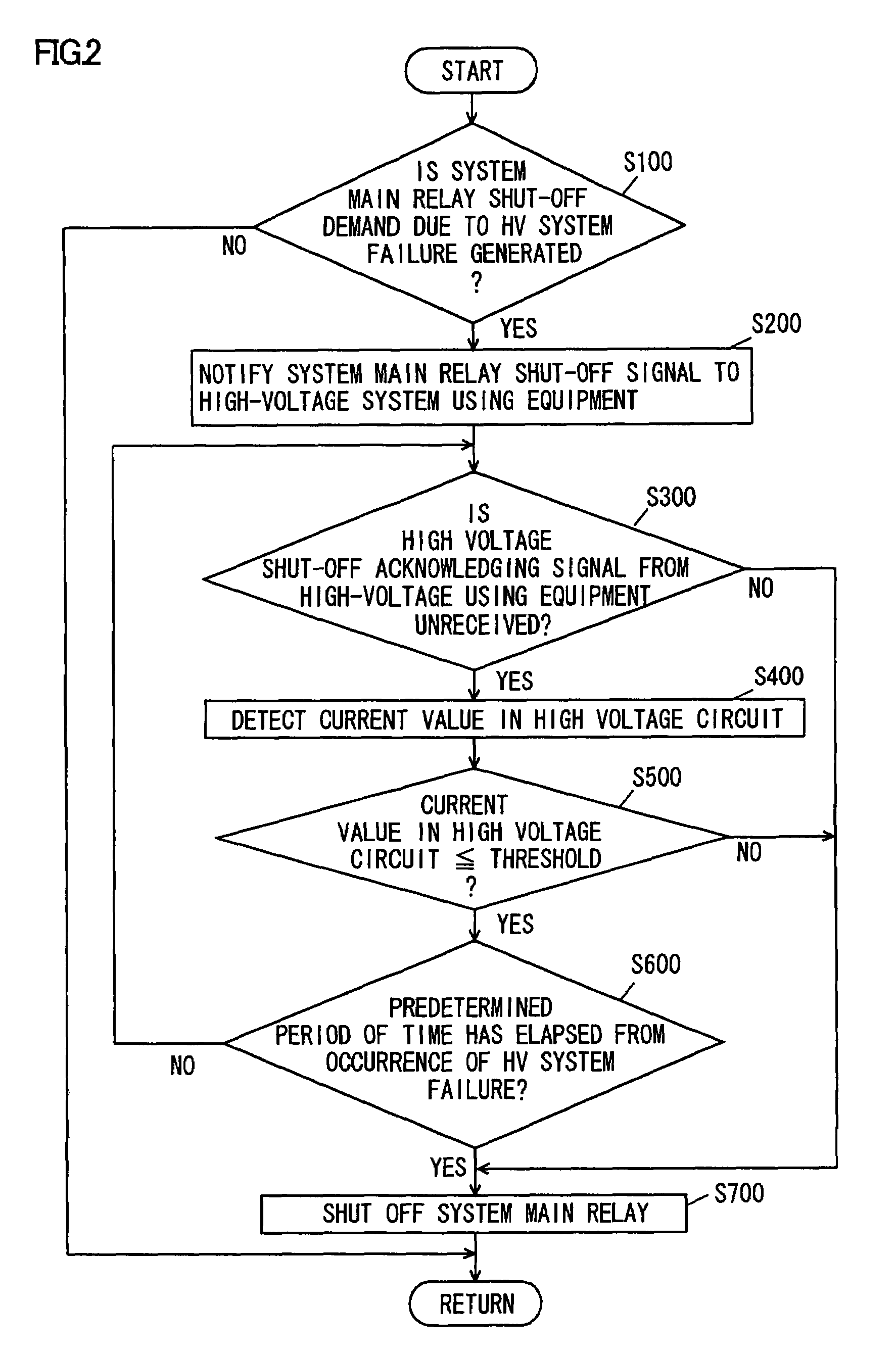
An ECU performs a program including a step of notifying a system main relay shut-off signal to a high-voltage system using equipment when a system main relay shut-off demand due to a HV system failure is generated, a step of shutting off the system main relay when a high voltage shut-off acknowledging signal from the high-voltage system using equipment is not unreceived, a step of shutting off the system main relay when a high voltage shut-off acknowledging signal from the high-voltage system using equipment is unreceived and a current value in a high voltage circuit is more than the predetermined threshold, and a step of shutting off the system main relay when the current value in the high voltage circuit is not more than the predetermined threshold and the predetermined period of time has elapsed from the occurrence of a HV system malfunction.

Description

TECHNICAL FIELD[0001]The present invention relates to an electrical load control device supplying a power from an energy storage mechanism to a plurality of electrical loads, and particularly to a control device in the case where the power supplied to the loads is shut off.BACKGROUND ART[0002]There has been developed and has come into practical use a vehicle on which a powertrain, which is called a hybrid system wherein an engine (for example, a well known engine such as a gasoline engine or a diesel engine is considered to be used) and an electric motor are combined, is mounded. Such a vehicle is controlled so as to achieve the most efficient performance by automatically switching between operation by the engine and operation by the electric motor regardless of an accelerator operation amount by a driver. For example, in the case where the engine is operated in a steady state and operated for rotating a generator that charges a secondary battery (battery) acting as an energy storag...

Claims


Application Information

Patent Timeline
Patent Type & Authority Patents(United States)
IPC IPC(8): B60L1/00B60Q1/00H02J3/38
CPCB60L3/003B60L3/0046B60L3/0061B60L3/04B60L11/1803B60L11/1868B60L2250/10Y02T10/7005Y02T10/7066B60L50/51B60L58/18B60L58/20Y02T10/70
Inventor HOSHIBA, TAKESHI
Owner TOYOTA JIDOSHA KK
Learn More