
Drive control device for vehicle with independently driven wheels

a technology of independent driving and control device, which is applied in the direction of electric propulsion mounting, electric devices, braking systems, etc., can solve the problems of vehicle unstability, vehicle behavior, and vehicle unstability, and achieve the effect of reliable and easy suppression

Active Publication Date: 2018-12-06
NTN CORP
View PDF12 Cites 3 Cited by
  • Summary
  • Abstract
  • Description
  • Claims
  • Application Information

AI Technical Summary

Benefits of technology

The invention is about a device that controls how a vehicle with independently driven wheels drives. This device helps prevent the vehicle from becoming unstable by controlling the torque of each wheel so they rotate at the same speed. This prevents unexpected yaw moments that can make the vehicle become unstable. Overall, this device ensures a smoother and more stable ride for the vehicle's occupants.

Problems solved by technology

In addition, such a difference in rotation speed is generated owing to also a difference of the diameters of tires due to a difference in wear or pneumatic pressure between the tires.
Accordingly, unexpected yaw moment can be generated on the vehicle, which causes the vehicle to behave unstably.
If the techniques of Patent Documents 1 to 3 are applied to a vehicle including left and right motors for individually driving left and right drive wheels, unexpected yaw moment is generated on the vehicle owing to such a difference in rotation speed between the left and right wheels as aforementioned, and the vehicle may behave unstably.

Method used


Image

  • Drive control device for vehicle with independently driven wheels
  • Drive control device for vehicle with independently driven wheels
  • Drive control device for vehicle with independently driven wheels

Examples


first embodiment

[0044]the present invention will be described with reference to FIG. 1 to FIG. 6.

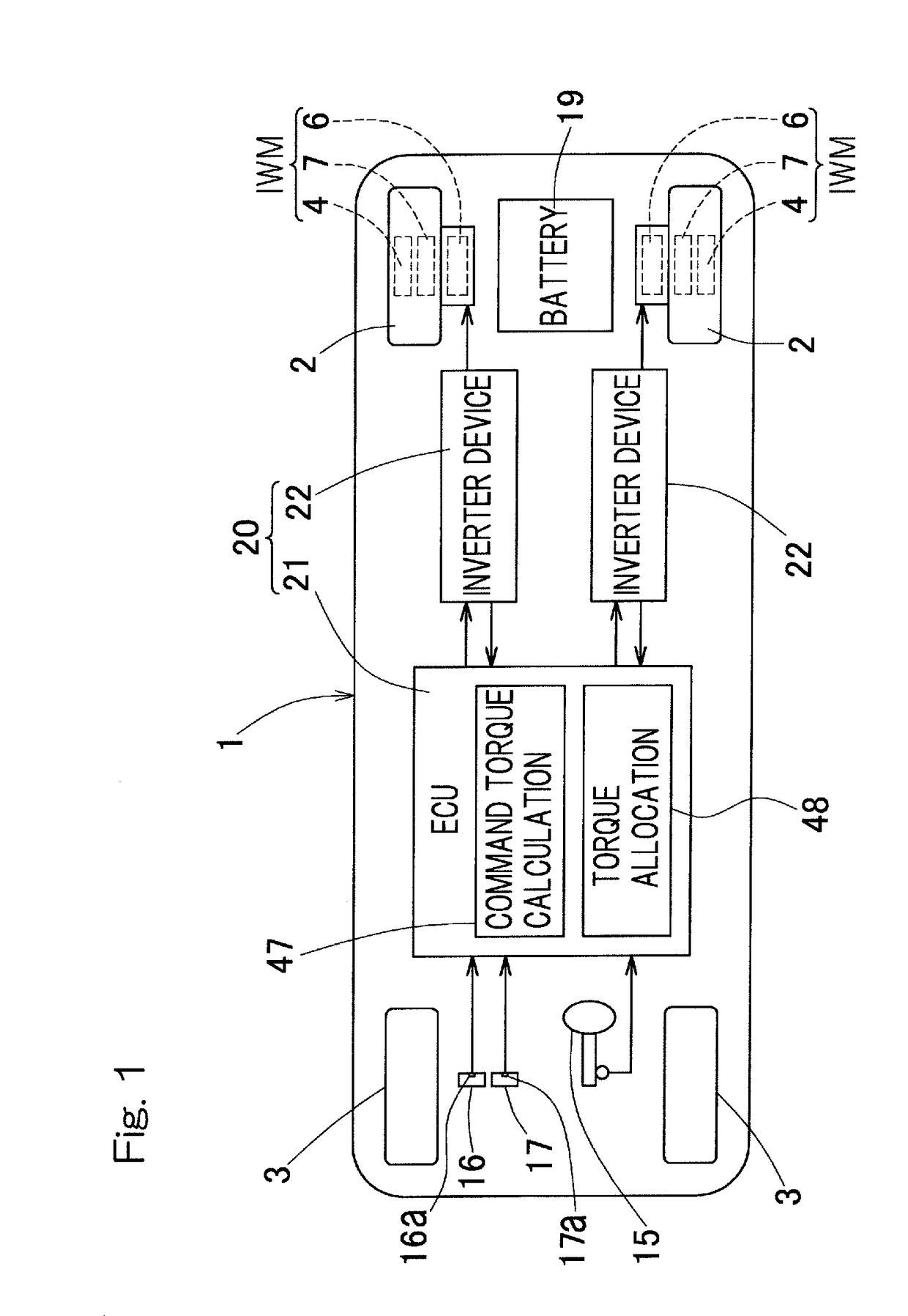
[0045]FIG. 1 is a block diagram of a schematic configuration of an electric vehicle, as viewed from the top, that is a vehicle equipped with a drive control device according to this embodiment. The electric vehicle is a four-wheel vehicle or an automobile. The electric vehicle includes a vehicle body 1, in which left and right rear wheels are drive wheels 2, 2 and left and right front wheels are driven wheels 3, 3. The front wheels 3, 3 are steered wheels. The left and right front wheels 3, 3 can be turned via a turning mechanism not shown, and are steered through a steering device 15 such as a steering wheel. The left and right drive wheels 2, 2 are driven by respective independent traction motors 6, 6. Each motor 6 constitutes an in-wheel motor drive device IWM described below. Each of the wheels 2, 3 is provided with a brake not shown.

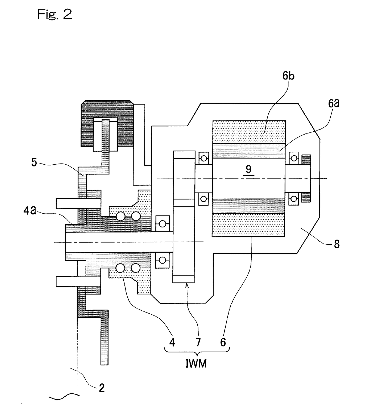
[0046]FIG. 2 is a cross-sectional view of the in-wheel motor drive...


PUM


Abstract

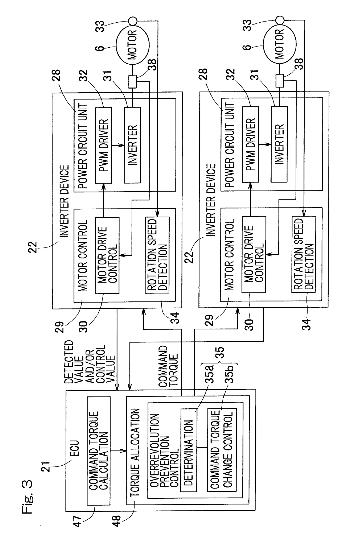
Provided is a drive control device for a vehicle with independently driven wheels, the control device enabling the vehicle to avoid unstable behavior caused by an overrevolution of one of the drive wheels. The vehicle includes left and right motors (6, 6) that independently drive left and right drive wheels (2, 2), respectively. The control device includes: an ECU (21) to generate and output a command torque; an inverter device (22); rotation speed detection modules (34, 34) to detect the rotation speeds of the respective left and right motors (6, 6); and a control module (35) to change the command torques for the respective left and right motors (6, 6) so as to reduce the rotation speeds of the left and right motors (6, 6) when at least one rotation speed between the detected rotation speeds of the left and right motors (6, 6) exceeds a predetermined rotation speed.

Description

CROSS REFERENCE TO THE RELATED APPLICATION[0001]This application is a continuation application, under 35 U.S.C. § 111(a), of international application No. PCT / JP2017 / 004650, filed Feb. 8, 2017, which claims Convention priority to Japanese patent application No. 2016-024414, filed Feb. 12, 2016, the entire disclosure of which is herein incorporated by reference as a part of this application.BACKGROUND OF THE INVENTIONField of the Invention[0002]The present invention relates to a drive control device for a vehicle with independently driven wheels, and more specifically, relates to a technique which allows a vehicle to avoid unstable behavior caused by an overrevolution of one of a pair of left and right drive wheels.Description of Related Art[0003]The following techniques have been proposed in order to perform control for preventing an overrevolution of a traction motor in an electric vehicle.[0004]1. Technique in which coasting or regeneration is performed when the rotation speed of ...

Claims


Application Information

Patent Timeline
Patent Type & Authority Applications(United States)
IPC IPC(8): B60L3/10
CPCB60L3/106B60L3/102B60L15/20B60L7/22B60L9/18B60K1/02B60L3/00B60T8/175B60L7/10B60Y2200/91B60W2520/28B60W30/02B60W2710/083Y02T10/64Y02T10/72B60L7/16B60L2220/42B60L2220/44B60L2240/423B60L2240/461B60W30/18127B60W30/18172B60K28/16
Inventor KANDA, TAKESHI
Owner NTN CORP
Learn More