Ion detection system with neutral noise suppression

a detection system and neutral noise technology, applied in the direction of instruments, particle separator tube details, separation processes, etc., can solve the problems of reducing the signal-to-noise ratio and thus sensitivity of the ion detector, restricting the ions exiting from the mass analyzer, and reducing the ion collection

Active Publication Date: 2008-12-16
ADAPTAS SOLUTIONS LLC
View PDF5 Cites 16 Cited by
  • Summary
  • Abstract
  • Description
  • Claims
  • Application Information

AI Technical Summary

Problems solved by technology

This action generates unwanted electrical signal and thereby reduces the signal-to-noise ratio, and thus sensitivity, of the ion detector.
However, this method will also restrict the ions exiting from the mass analyzer and reduce the ion collection.
In an effort to increase detector sensitivity, the electron multiplier can be biased as high as the conversion dynode but this has proven to be impractical.
If any such neutrals are present at the ion exit of a mass analyzer, neutral noise will be generated.
This effect contributes to neutral noise in a mass spectrum.
These two features provide a method to reduce neutral noise, but at the cost of reduced ion collection efficiency resulting from lens aperture constrictions.

Method used


Image

  • Ion detection system with neutral noise suppression
  • Ion detection system with neutral noise suppression
  • Ion detection system with neutral noise suppression

Examples


Embodiment Construction

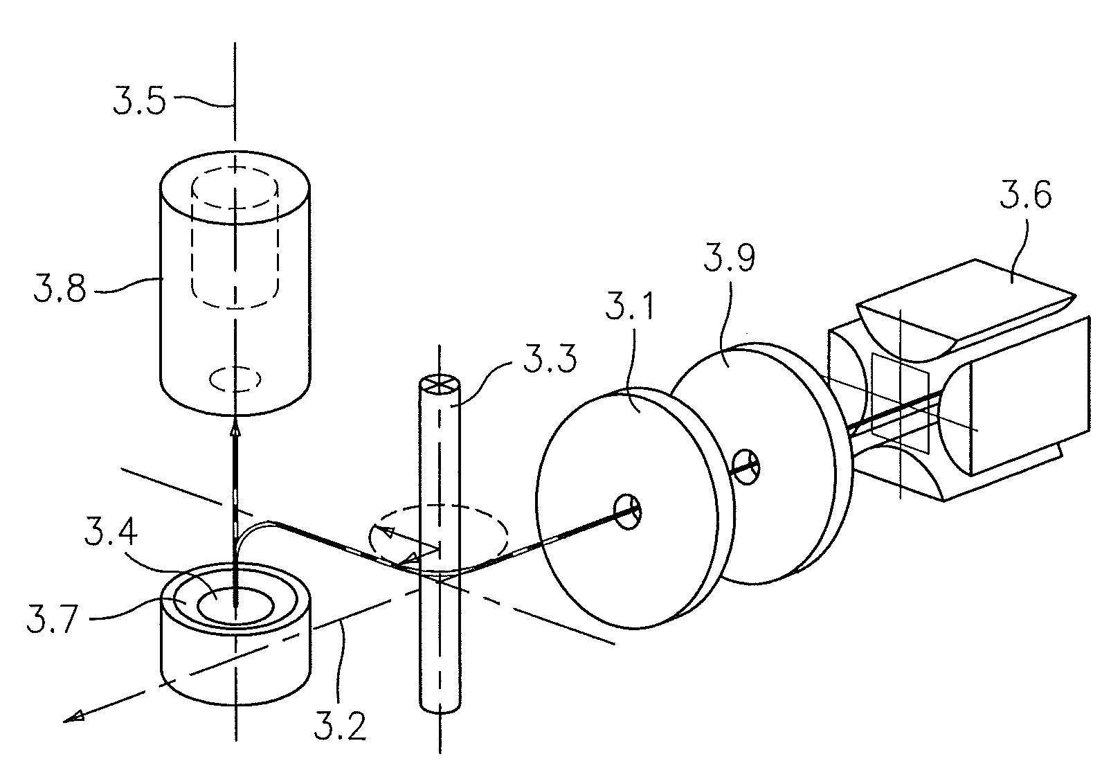
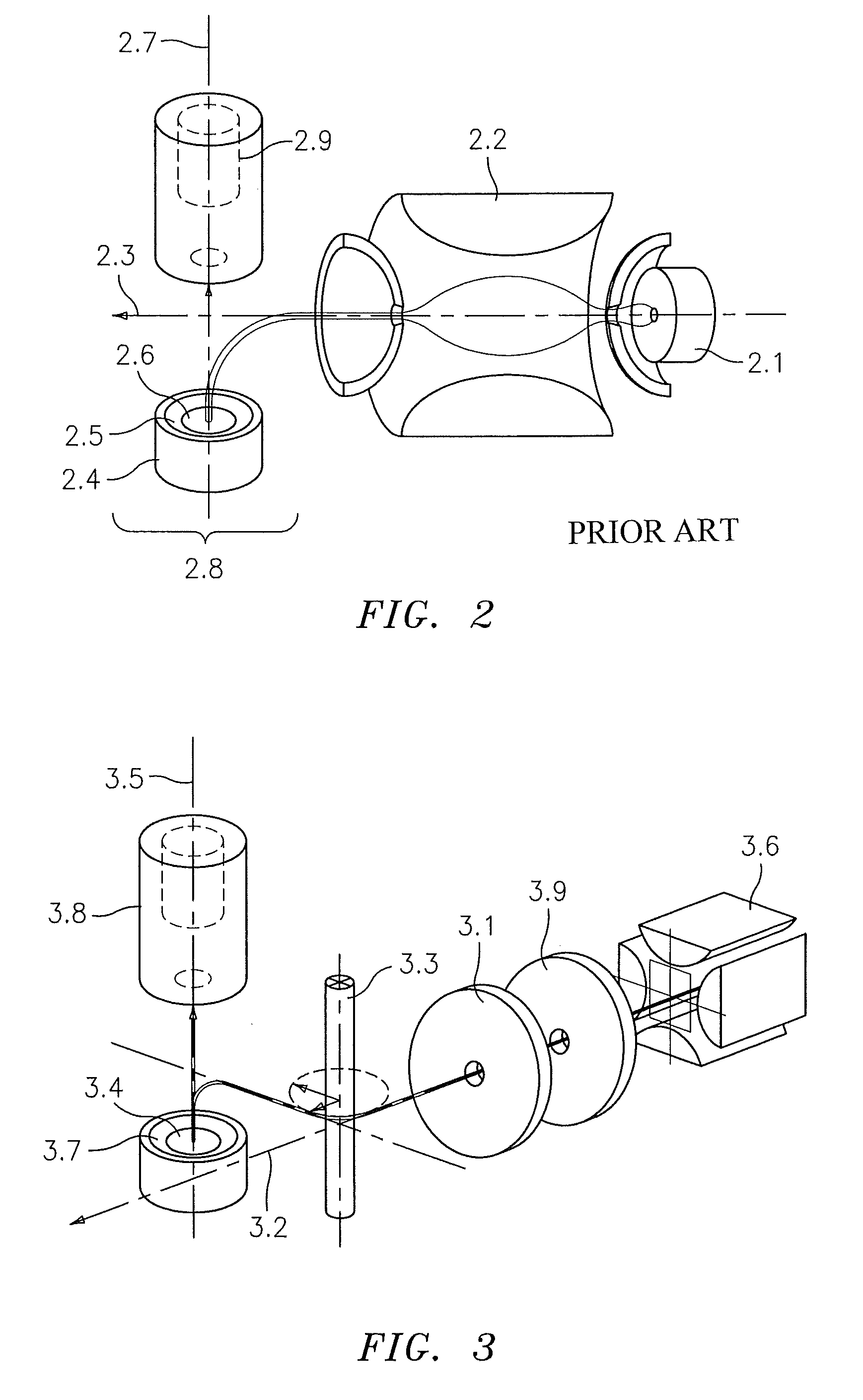
[0015]FIG. 3 illustrates an ion optics configuration for suppression of neutral noise. The conversion dynode is positioned such that the conversion dynode axis 3.5 that passes through the center of the ion collision region 3.4 of the conversion dynode and perpendicular to the dynode collision surface 3.7 does not intersect the longitudinal axis 3.2 of the ion exit beam of the quadrupole mass analyzer 3.6. That is, the axis 3.5 collinear to the conversion dynode region 3.4 and the input port of the electron multiplier 3.8 does not intersect the longitudinal axis 3.2 of the ion beam exiting from the mass analyzer 3.6.

[0016]In the embodiment of FIG. 3, the trajectory of ions exiting the mass analyzer 3.6 is bent and projected to the ion collision region of the conversion dynode. To achieve this redirection of the ion beam, a field generator in the form of a conducting bending rod 3.3 is positioned adjacent to the axis 3.2 of the ion beam. The conducting bending rod 3.3 is negatively or...


PUM


Abstract

An ion detection system includes a mass analyzer generating an ion beam along an ion beam longitudinal axis. A field generator generates a field for altering the direction of ions in the ion beam away from the ion beam longitudinal axis. A conversion dynode includes an ion collision region on a conversion dynode surface. A conversion dynode axis passes through the ion collision region perpendicular to the conversion dynode surface, the conversion dynode axis being offset from and not intersecting the ion beam longitudinal axis. An electron multiplier receives secondary charged particles from the conversion dynode generated in response to the ion collision with the conversion dynode surface.

Description

BACKGROUND OF THE INVENTION[0001]Most of the industry standard ion detectors in mass spectrometers are equipped with high voltage conversion dynodes to enhance ion detection, especially for ions having high molecular masses. Ions exiting from a mass analyzer, such as a quadrupole mass filter, are projected to a high voltage conversion dynode so that their collisions with the dynode cause secondary charged particles to be radiated from the dynode surface. These secondary charged particles are repelled by the dynode so as to direct and focus them into the input port of an electron multiplier (e.g., either continuous channel or discrete dynode construction) in order to generate an electrical pulse for further signal processing. Additional ion optic lenses may be installed to increase ion collection from the mass analyzer.[0002]In mass spectrometers, the conversion dynode is positioned such that the axis of symmetry of the ion impact region, on the dynode surface, intersects with the ax...

Claims


Application Information

Patent Timeline
Patent Type & Authority Patents(United States)
IPC IPC(8): H01J37/244H01J49/26
CPCH01J49/025H01J49/061H01J49/26
Inventor HOSEA, KIKI H.BREUER, MATTHEW L.
Owner ADAPTAS SOLUTIONS LLC
Why Eureka
Try Eureka