
Drive assembly for locking one or several operating units of an agricultural implement or of a self-propelled implement

a technology of driving assembly and operating unit, which is applied in the direction of agricultural machines, slip couplings, gearing, etc., can solve the problems of large number of to be driven operating units in agricultural implements and self-propelled implements, and damage to the operating uni

Inactive Publication Date: 2008-12-16
JEAN WALTERSCHEID GMBH
View PDF29 Cites 59 Cited by
  • Summary
  • Abstract
  • Description
  • Claims
  • Application Information

AI Technical Summary

Benefits of technology

[0005]It is an object of the present invention to provide a method where the drive unit is protected from overloading when the operating unit is locked. Also, the operating unit is stopped as quickly as possible.
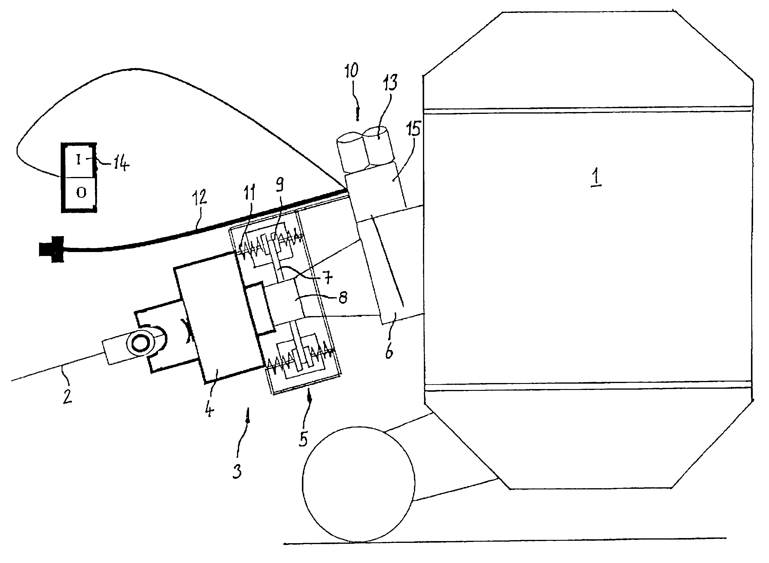
[0007]In this way, it is possible to brake and lock the large masses of the operating unit which continue to run. Thus, rotating masses no longer constitute a risk. By arranging the brake unit between the overload coupling and the operating unit, the brake unit can be actuated even while the drive unit is running. The overload coupling is disconnected as a result of the braked operating unit. Also, the power flow is interrupted.
[0011]In this way, it is possible for the brake unit to be braked automatically if a foreign body enters into the operating range or when an object enters the operating range of an implement. The object may cause damage to the implement. The manually operable mechanism to release the brake unit can be arranged in the driver's cab. Thus, the brake unit may be released only when the driver is no longer in the operating range.

Problems solved by technology

As a rule, the masses of the to be driven operating units in agricultural implements and self-propelled implements are very large.
This may cause damage to the operating unit.

Method used


Image

  • Drive assembly for locking one or several operating units of an agricultural implement or of a self-propelled implement
  • Drive assembly for locking one or several operating units of an agricultural implement or of a self-propelled implement

Examples


Embodiment Construction

[0018]The following description of the preferred embodiment(s) is merely exemplary in nature and is in no way intended to limit the invention, its application, or uses.

[0019]The FIGURE shows an agricultural implement 1 which is pulled or driven by a tractor. A driveline to drive the agricultural implement 1 includes a driveshaft 2. On one side, the driveshaft 2 is connected to a power take-off shaft of the tractor. On the other side, the driveshaft 2 is connected to a drive assembly 3 of the driveline. The drive assembly 3 includes an overload coupling 4. The overload coupling 4 may be a form-fitting, force-locking or friction-locking overload coupling. The overload coupling 4 is connected to the driveshaft 2 on one side and to a brake unit 5 on the other. The brake unit 5, in turn, with respect to drive, is connected to an operating unit 6 of the agricultural implement 1. Thus, it is possible to transmit driving torque from the power take-off shaft of the tractor, via the driveshaf...


PUM


Abstract

A drive assembly driven by a drive unit locks one or several operating units (6) of an agricultural implement (1) or of a self-propelled implement. The operating unit (6) can be locked when switching off the drive unit or upon reaction of an overload coupling (4). The drive assembly (3) has an overload coupling (4) connected to the drive unit and driven by the drive unit in one driving direction of rotation. The overload coupling (4) is also connected to the operating unit (6). The drive assembly (3) further has a brake unit (5) connected to the overload coupling (4). The brake unit (5) is intended to be arranged in the driveline between the overload coupling (4) and the operating unit (6). Actuating mechanism (10) actuates the brake unit (5) when the operating unit is running so that the operating unit is braked and locked. Thereafter, the overload coupling is disconnected.

Description

CROSS-REFERENCE TO RELATED APPLICATION[0001]This application claims priority to German Patent Application No. 10145407.4, filed Sep. 14, 2001, which application is herein expressly incorporated by reference.FIELD OF THE INVENTION[0002]The invention relates to a drive assembly for locking one or several operating units of an agricultural implement or of a self-propelled implement in an emergency. Locking is affected by a drive assembly driven by a drive unit in a driveline.BACKGROUND OF THE INVENTION[0003]Prior art agricultural implements or self-propelled implements such as bailing presses, mowing machines or harvesting machines have operating units which are driven by a drive unit, as a rule by an internal combustion engine. An overload coupling is provided in the driveline between the drive unit and the operating unit. The overload coupling prevents any damage to the operating unit in the case of overloading. Overload couplings are in the form of form-fitting overload couplings su...

Claims


Application Information

Patent Timeline
IPC IPC(8): A01D75/18A01B61/02A01F15/08
CPCA01B61/025A01F15/0841A01D75/20
Inventor COENEN, KARL
Owner JEAN WALTERSCHEID GMBH
Learn More