
Multiple combustion mode engine using direct alcohol injection

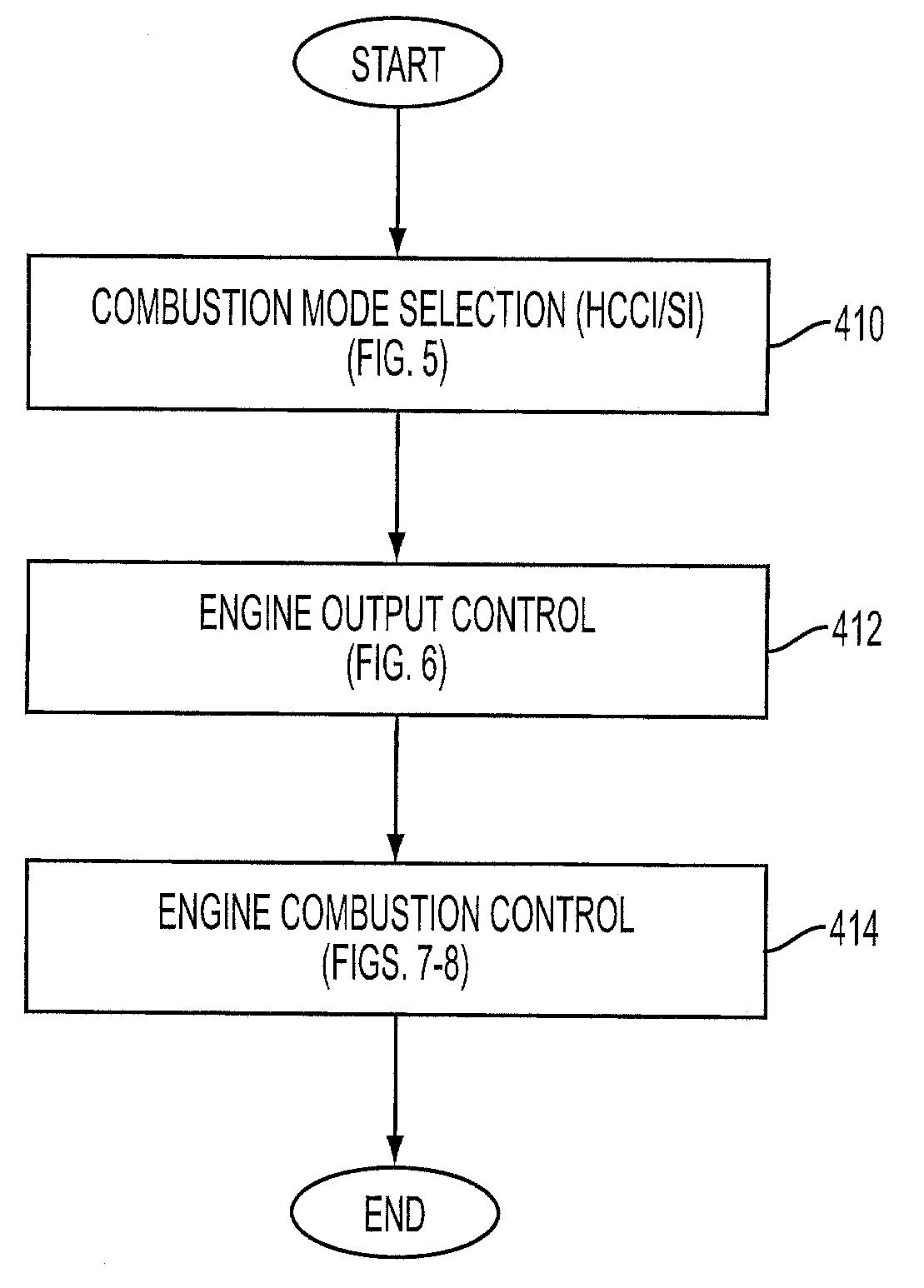
a technology of direct alcohol injection and combustion mode, which is applied in the direction of machines/engines, electrical control, instruments, etc., can solve the problems of pcci (premixed charge compression ignition), the operation of hcci and similar modes of operation may be limited to low loads (torque), and the present control problems, etc., to achieve the effect of increasing the compression ratio, reducing the number of engine components, and expanding the hcci design rang

Active Publication Date: 2008-12-09
FORD GLOBAL TECH LLC +1
View PDF176 Cites 75 Cited by
  • Summary
  • Abstract
  • Description
  • Claims
  • Application Information

AI Technical Summary

Benefits of technology

This approach allows for higher compression ratio operation without knock limitations, enhancing HCCI design range and spark ignition fuel economy, while also controlling HCCI combustion timing for improved transient performance, resulting in increased efficiency and reduced emissions.

Problems solved by technology

While HCCI may have greater fuel efficiency and reduced NOx production compared to other combustion modes under selected conditions, it may also be limited since a substantial amount of heat and pressure may be needed to produce combustion.
Further, transitions into and out of the HCCI mode may present various control issues.
However, HCCI operation and similar modes of operation, such as PCCI (Premixed Charge compression ignition, where there is stratification of the air / fuel mixture) may be limited to low loads (torque).
However, while spark retard may mitigate engine knock, this can reduce engine fuel efficiency.
As such, engines may need to operate at lower actual or effective compression ratios during SI combustion to avoid knock.
Thus, a general incompatibility may exist between the higher compression ratio preferred for HCCI operation and the lower compression ratio for SI operation, limiting the benefits that can be achieved.
While some adjustment to compression ratio may be available via variable valve timing, variable valve lift, variable compression ratio, etc., the degree of adjustment necessary may require significant amounts of additional engine hardware and increased cost.
Further, even if such hardware is present, the ability to rapidly and effectively control both knock and compression ignition may be limited by the time characteristics of the mechanical device transitions, etc.

Method used


Image

  • Multiple combustion mode engine using direct alcohol injection
  • Multiple combustion mode engine using direct alcohol injection
  • Multiple combustion mode engine using direct alcohol injection

Examples


Embodiment Construction

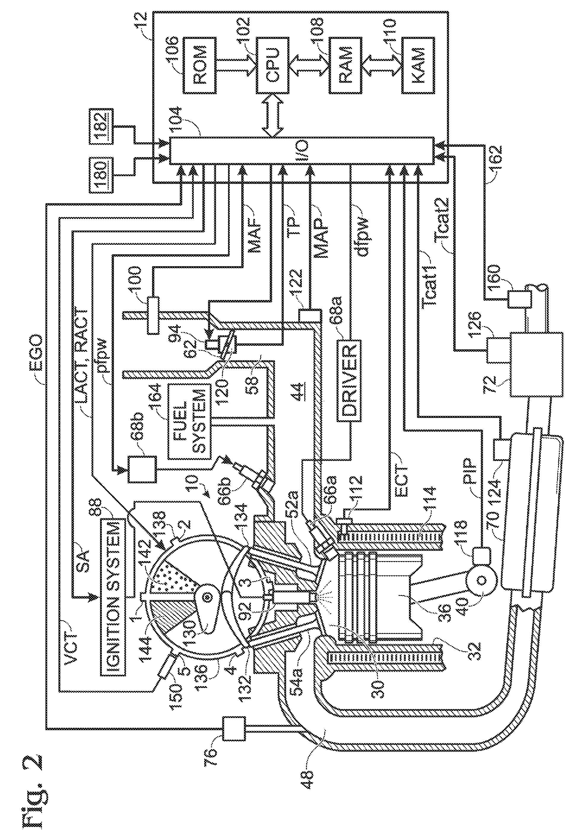
[0012]Gasoline engines, particularly those with a boosting device, may employ a variable direct injection of a knock suppressing fuel such as an alcohol or alcohol blend to provide improved performance. As one prophetic example, an engine including a turbocharger and a high compression ratio along with selective and variable ethanol direct injection in addition to gasoline injection may achieve a 20%-30% increase in efficiency over a naturally aspirated spark ignition engine of larger size delivering the same torque and power. The directly injected ethanol provides a large knock suppression effect from the evaporative cooling of the fuel / air charge within the cylinder of the engine. This improvement in efficiency can enable the engine to be substantially downsized and / or operate at a higher compression ratio while providing a similar level of performance. These efficiency gains may be even further increased by use of a controlled auto-ignition e.g. a homogeneous charge compression i...


PUM


Abstract

A method of operating an engine, comprising of performing homogeneous charge compression ignition combustion during a first operating condition, and performing spark ignition combustion during a second operating condition, where an amount of directly injected alcohol in at least one of said homogeneous charge compression ignition combustion and said spark ignition combustion is varied in response to at least an operating parameter.

Description

BACKGROUND AND SUMMARY[0001]Internal combustion engines may operate in a variety of combustion modes. One example mode is homogeneous charge compression ignition (HCCI), wherein a homogeneous or near homogeneous air and fuel mixture achieves a temperature and / or pressure where combustion occurs by auto-ignition without requiring a spark being performed by a sparking device. Auto-ignition timing may be varied by adjusting one or more of the initial charge temperature, amount of residual or recirculated exhaust gas, actual and / or effective compression ratio, etc. While HCCI may have greater fuel efficiency and reduced NOx production compared to other combustion modes under selected conditions, it may also be limited since a substantial amount of heat and pressure may be needed to produce combustion. Further, transitions into and out of the HCCI mode may present various control issues. In general, HCCI combustion may be enhanced over a wider operating range by increasing the compressio...

Claims


Application Information

Patent Timeline
Patent Type & Authority Patents(United States)
IPC IPC(8): F02M43/04F02M43/00
CPCF02B11/00F02B17/005F02D19/081F02D35/027F02D41/0025F02D41/3035F02D41/3064F02D19/061F02D19/0655F02D19/0689F02D19/0692F01N11/00F01N11/002F02B1/12F02D2041/001Y02T10/128Y02T10/36F02D19/084Y02T10/12Y02T10/30
Inventor BLUMBERG, PAULBROMBERG, LESLIECOHN, DANIEL R.HEYWOOD, JOHN B.DAVIS, GEORGEZUBECK, MICHAELSTEIN, ROBERT
Owner FORD GLOBAL TECH LLC
Learn More