Inkjet head
a technology of inkjet head and adhesive, which is applied in the direction of printing and inking apparatus, etc., can solve the problems of affecting the electrical insulation properties of at least one of the piezoelectric elements, affecting the adhesion of adhesive to the upper face (face opposite), and affecting the mechanical strength of the piezoelectric elemen
- Summary
- Abstract
- Description
- Claims
- Application Information
AI Technical Summary
Benefits of technology
Problems solved by technology
Method used
Image

Examples
first embodiment
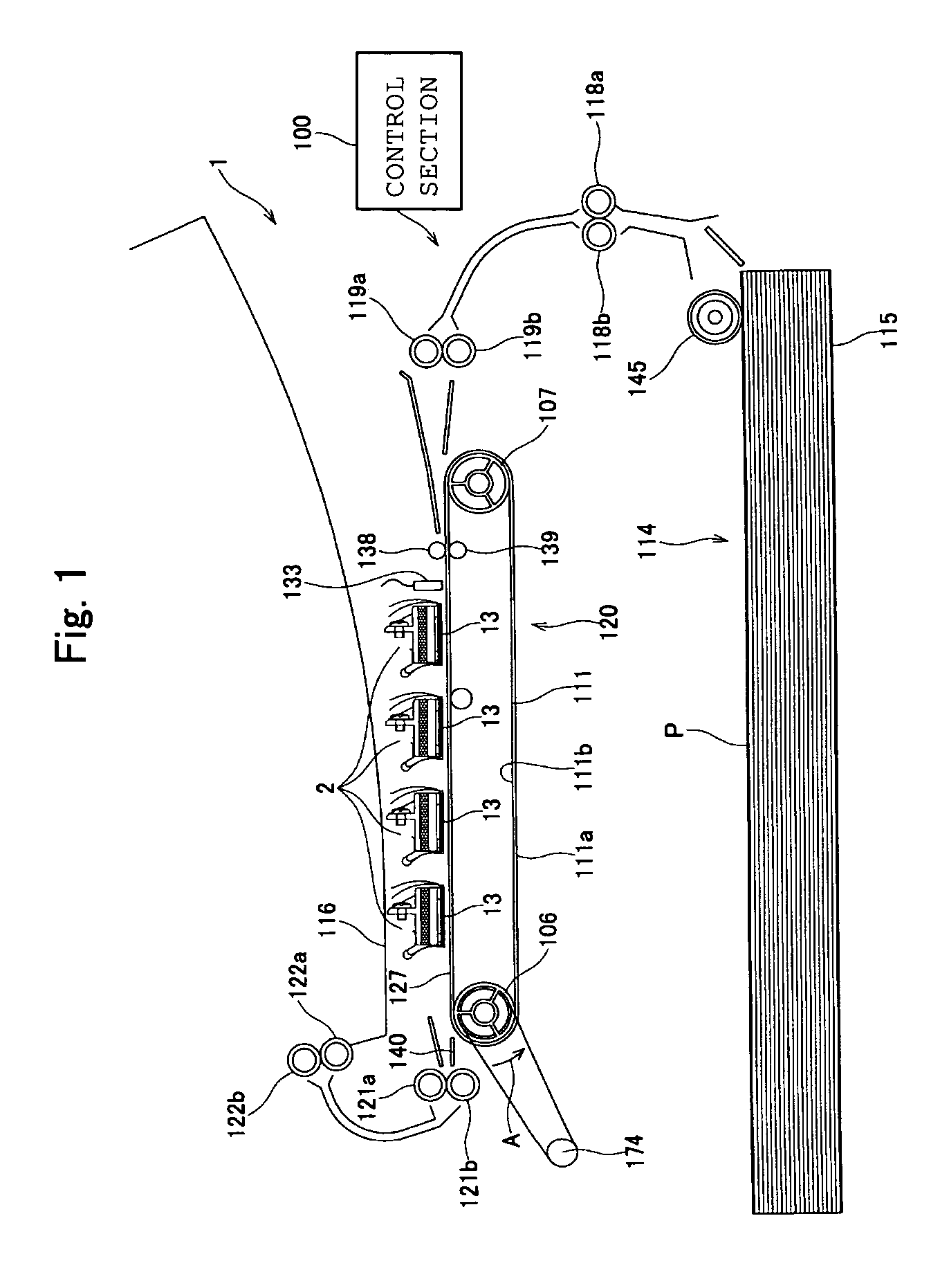
[0022]First of all, an inkjet head according to a first embodiment of the present invention will be described. FIG. 1 shows a printer 1 including an inkjet head 2 according to this embodiment. The printer shown in FIG. 1 is a line head type color inkjet printer having four fixed inkjet heads 2 of rectangular shape in plan view elongated in a direction orthogonal to the plane of FIG. 1. The printer 1 is provided with a paper feed device 114 at the bottom in the Figure, a paper receiving section 116 at the top in the Figure and a paper feed unit 120 at the middle in the Figure, respectively. In addition, the printer 1 comprises a control section 100 that controls the operation of these.
[0023]The paper feed device 114 comprises a paper sheet accommodating section 115 capable of accommodating a plurality of stacked rectangular printing paper sheets P and paper feed roller 145 that feeds the uppermost sheet of printing paper P in the paper sheet accommodating section 115, one sheet at ti...
second embodiment
[0068]Next, an inkjet head according to a second embodiment of the present invention is described below with reference to FIG. 12. The inkjet head according to this embodiment differs from the inkjet head 2 of the first embodiment solely in that a step is formed on the end face of the actuator unit. The following description will therefore focus on the differences between these two. Also, members which are the same as in the description of the first embodiment are given the same reference symbols and further description thereof is dispensed with.
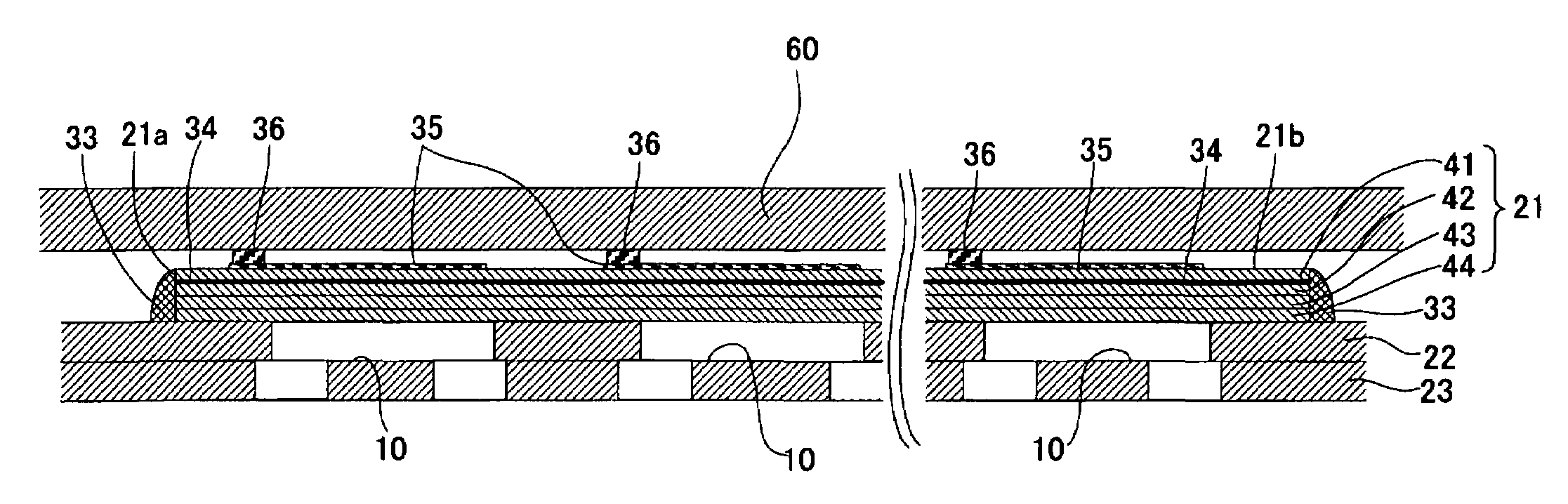
[0069]As shown in FIG. 12, in an inkjet head according to this embodiment, an actuator unit 71 comprises four piezoelectric sheets 41′, 42, 43, 44 of the same thickness. The piezoelectric sheet 41′ is of slightly smaller planar size than the remaining three piezoelectric sheets 42 to 44. A step having an upwardly directed step face 71c is therefore formed over the entire periphery in the end face 71a of the actuator unit 71. A common electro...
example 1
[0073]The state of sealing of the end face 21a and the state of adhesion of adhesive onto the upper face 21b of the actuator unit 21 were observed when only the thickness of the actuator unit 21 was varied in nine steps, namely, 10, 15, 20, 25, 40, 80, 100, 110, and 150 μm in an inkjet head 2 as described in the first embodiment. The results are shown in Table 1. The details of the inkjet head 2 that was used were as follows.
[0074]
TABLE 1ActuatorState of adhesionthicknessState of sealingof adhesive on(μm)of end faceupper faceEvaluation10good sealingadhesion in apoorwide range15good sealingpartial adhesionmoderate20good sealingno adhesiongood25good sealingno adhesiongood40good sealingno adhesiongood80good sealingno adhesiongood100good sealingno adhesiongood110some poorno adhesionmoderatesealing150poor sealingno adhesionpoor
[0075]In Table 1, “good sealing” means that sealing is effected uniformly without exposure of the end faces over the entire region. As can be seen from Table 1, th...
PUM
 Abstract
Description
Claims
Application Information
 - R&D
- Intellectual Property
- Life Sciences
- Materials
- Tech Scout
- Unparalleled Data Quality
- Higher Quality Content
- 60% Fewer Hallucinations
Browse by: Latest US Patents, China's latest patents, Technical Efficacy Thesaurus, Application Domain, Technology Topic, Popular Technical Reports.
© 2025 PatSnap. All rights reserved.Legal|Privacy policy|Modern Slavery Act Transparency Statement|Sitemap|About US| Contact US: help@patsnap.com