Transducer and transducer arrangement for ultrasonic probe systems, ultrasonic probe system and inspection method

a technology of ultrasonic probes and transducers, applied in the direction of instruments, measurement devices, and analysis of solids using sonic/ultrasonic/infrasonic waves, can solve the problems of high device technology requirements and longer inspection times, and achieve the effect of promoting simplified structure and effective functionality

Active Publication Date: 2022-08-09
BUNDESREPUBLIK DEUT VERTRETEN DURCH DEN BUNDESMINIST FUR WIRTSCHAFT & ENERGIE
View PDF13 Cites 0 Cited by
  • Summary
  • Abstract
  • Description
  • Claims
  • Application Information

AI Technical Summary

Benefits of technology

[0004]The present invention describes a simplified ultrasonic probe system and an improved inspection method for detecting faults in a material, particularly in rails. Moreover, transducers and transducer arrangements for an ultrasonic probe system are presented, which promote the simplified structure and effective functionality of the latter.
[0005]By way of example, the transducers according to the invention facilitate a high energy influx into the material to be inspected and facilitate simultaneous coverage of a plurality of insonation angles at the same time. Since a defect in the material can only be detected if the echo therefrom is also received, the geometric arrangement between transmitter, receiver and the defect is moreover decisive. The transducer arrangement according to the invention allows simultaneous coverage of a plurality of insonation angles and largely prevents the superposition of soundwaves that are coupled into the material by different transducers. Moreover, the transducer arrangement according to the invention can be housed in only a single probe or in a few probes and thereby causes a significantly simplified structure of the ultrasonic probe system according to the invention in comparison with conventional ultrasonic systems, without fewer inspection angles being considered during the inspection of a material in this case.

Problems solved by technology

In general, the phased-array technique places high demands on the device technology and requires longer inspection times in comparison with the inspection using a plurality of fixed-angle probes operating in parallel.

Method used


Image

  • Transducer and transducer arrangement for ultrasonic probe systems, ultrasonic probe system and inspection method
  • Transducer and transducer arrangement for ultrasonic probe systems, ultrasonic probe system and inspection method
  • Transducer and transducer arrangement for ultrasonic probe systems, ultrasonic probe system and inspection method

Examples


Embodiment Construction

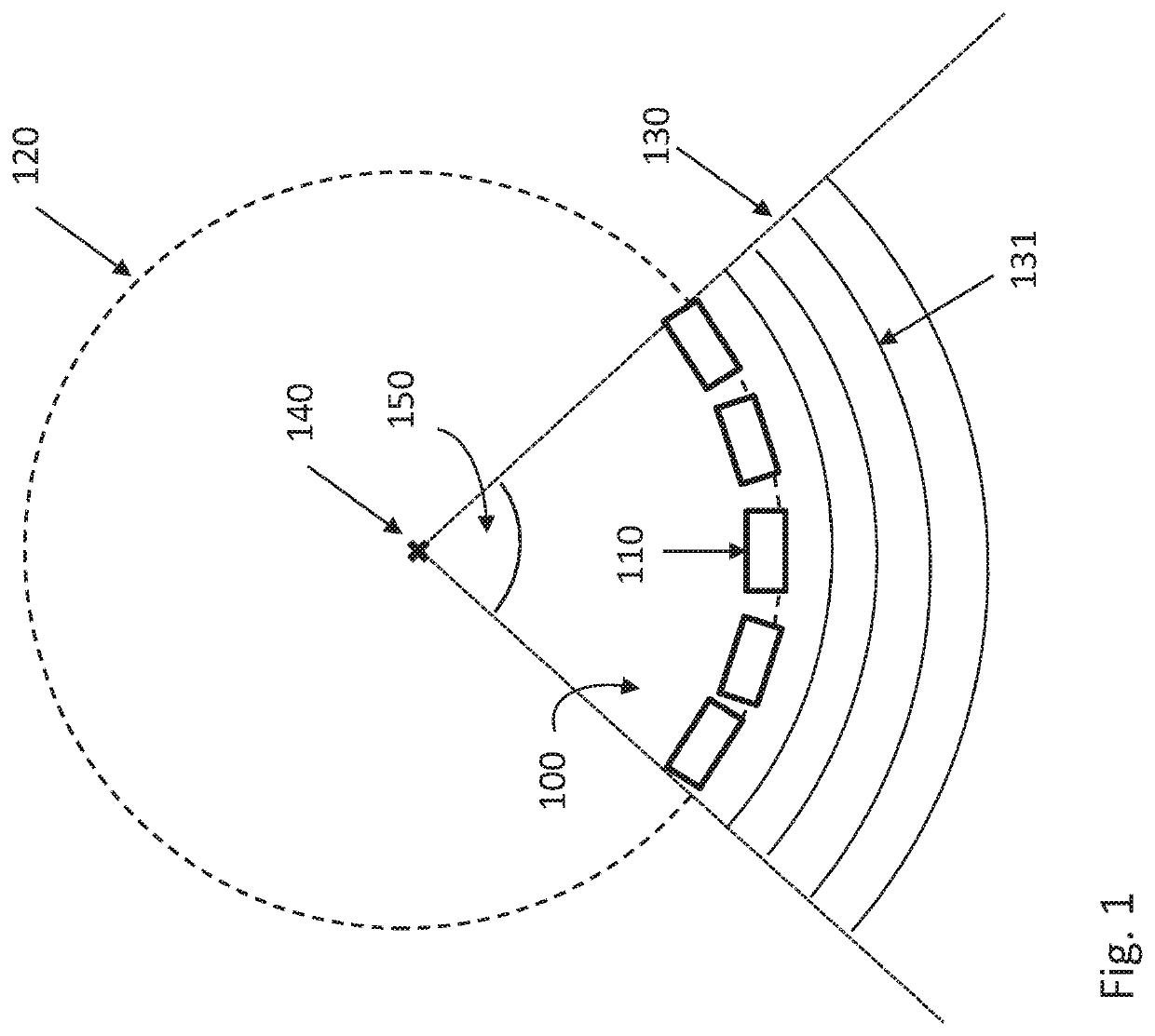
[0014]FIG. 1 shows an embodiment of a transducer 100 according to the invention comprising 5 transducer elements 110, which are disposed on a circular arc of a virtual circle 120. Consequently, the transducer elements 110 form a curved linear array (1D array). The transducer elements 110 serve to transmit and receive soundwaves and, in particular, can be ultrasonic transducer elements such as piezo-elements, for example. According to the invention, the arrangement of the transducer elements 110 is designed in such a way that the soundwaves emitted by the transducer elements 110 are overlaid in such a way that they approximate a sector of an elementary wave 130, the virtual point source 140 of which is located at the center of the virtual circle 120. Here, an elementary wave is understood to mean a circular or spherical wave which propagates in all directions from one point. Consequently, the transducer 100 according to the invention emulates part of a concentric wavefront of a point...


PUM

PropertyMeasurementUnit
internal anglesaaaaaaaaaa
insonation anglesaaaaaaaaaa

Abstract

Described are a transducer made of at least three transducer elements which approximate a sector of an elementary wave with a virtual point source, and a transducer arrangement with three transducers made of at least three transducer elements, wherein the transducers, in the cross section, are disposed along the shorter base and the two non-parallel legs of a virtual trapezoid. Moreover, the invention relates to an ultrasonic probe system comprising the transducer arrangement according to the invention and an inspection method using a transducer made of at least three transducer elements, with the number of transducer elements experiencing a virtual increase.

Description

BACKGROUND OF THE INVENTION[0001]The present invention relates to transducers and transducer arrangements for ultrasonic probe systems, an ultrasonic probe system and inspection methods for detecting defects in a material, particularly in rails.[0002]Ultrasonic inspection has proven its worth for nondestructive testing of materials, particularly in the interior and at inaccessible surfaces. To this end, an ultrasonic transducer, which is able to transmit and receive ultrasonic pulses, is guided over an accessible surface of the material to be inspected, with a coupling medium such as water or oil usually being located between the ultrasonic transducer and the surface of the material. A connected device generates the electrical transmission pulses and receives the electrical signals from the ultrasonic transducer, which arise there if an echo reflected or scattered at the back wall or a defect of the material, for example, arrives at said ultrasonic transducer. By way of example, the...

Claims


Application Information

Patent Timeline
Patent Type & Authority Patents(United States)
IPC IPC(8): G01N29/07G01N29/22G01N29/24
CPCG01N29/2487G01N29/07G01N29/225G01N2291/051G01N2291/056G01N2291/106G01N2291/2623G01N29/043G01N2291/105G01N29/262G01N29/221G01N2291/044G01N2291/0289G01N29/265
Inventor HECKEL, THOMASBOEHM, RAINER
Owner BUNDESREPUBLIK DEUT VERTRETEN DURCH DEN BUNDESMINIST FUR WIRTSCHAFT & ENERGIE
Why Eureka
Try Eureka