Controllable coolant pump having a fluidic actuator

a technology of fluidic actuator and controllable coolant pump, which is applied in the direction of engine control, engine cooling apparatus, mechanical apparatus, etc., can solve the problems of requiring a large installation space and the final control unit is heavy, and achieve the effect of reducing the weight and the necessary installation space of the controllable coolant pump, and in particular the internal combustion engin

Inactive Publication Date: 2014-09-18
SCHAEFFLER TECH AG & CO KG
View PDF0 Cites 2 Cited by
  • Summary
  • Abstract
  • Description
  • Claims
  • Application Information

AI Technical Summary

Benefits of technology

The present invention provides a controllable coolant pump for an internal combustion engine that has reduced weight and space requirements. The pump has a reduced weight and takes up less installation space than traditional coolant pumps. The pressure of the coolant pump can be controlled, and the pump is designed to be continuously controlled. The pump uses a fluidic actuator to control the coolant pump, which allows for a continuous control of the pump. The pump has a simple construction, with a fluid-permeable first and second pressure chamber for supplying and discharging fluid. The pump is actuated by a spring element, which ensures a return of the push rod to its original position in case of failure. The use of the controllable coolant pump reduces the weight and space requirements of the engine.

Problems solved by technology

The disadvantage of a configuration of this type is that controlling the coolant flow with the aid of the piston and the final control unit makes for a heavy weight and requires a great deal of installation space.

Method used


Image

  • Controllable coolant pump having a fluidic actuator
  • Controllable coolant pump having a fluidic actuator
  • Controllable coolant pump having a fluidic actuator

Examples


Embodiment Construction

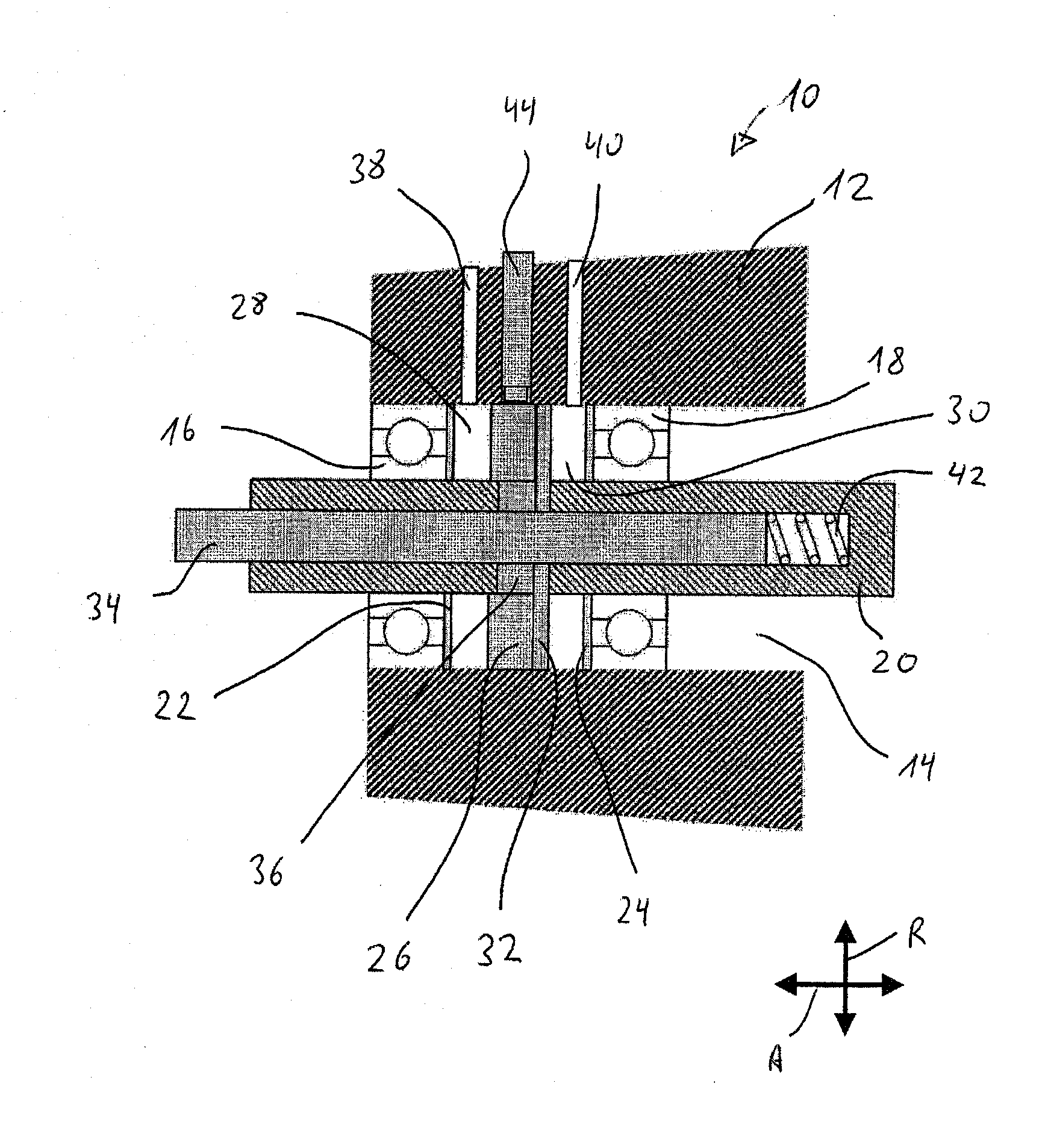
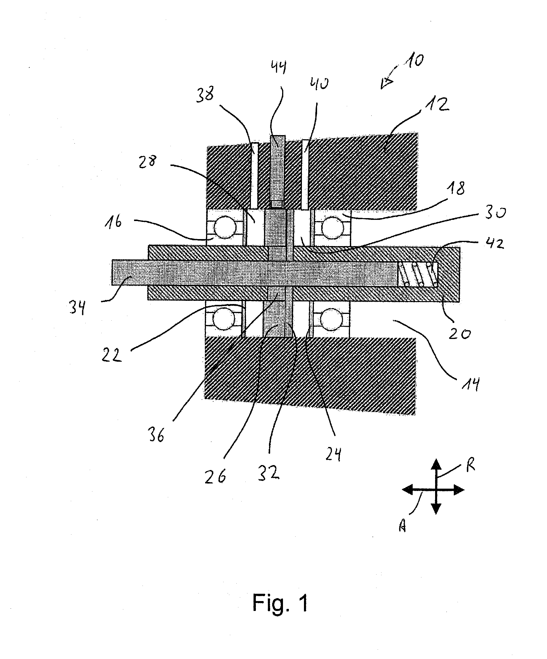
[0026]FIG. 1 shows a controllable coolant pump 10, which has a pump housing 12, including an inner bore 14. A first bearing 16 is situated within inner bore 14, and a second bearing 18 is situated at an axial distance therefrom. A shaft 20 is rotatably situated in first bearing 16 and second bearing 18 within inner bore 14 of pump housing 12. Between first bearing 16 and second bearing 18, an annular first seal 22 is situated on first bearing 16, and an annular second seal 24 is situated on second bearing 18. First seal 22 and second seal 24 form an essentially fluid-impermeable seal in the axial direction. A sealing ring 26, which is movably supported in the axial direction between first seal 22 and second seal 24, is situated between first bearing 16 and second bearing 18 and first seal 22 and second seal 24. A first pressure chamber 28, which is delimited in the radial direction by shaft 20 and pump housing 12, is provided between first seal 22 and sealing ring 26 in the axial di...


PUM


Abstract

A controllable coolant pump for a cooling circuit of an internal combustion engine having a pump housing with an inner bore, a shaft drivable via a pulley mounted rotatably via a first bearing and a second bearing, wherein the shaft is configured at least partially as a hollow shaft and has a longitudinal axis, wherein a rotor is fastened to one end of the shaft, which rotor has an idler pulley and vanes which project into a suction chamber to suck water via a suction connector of the pump housing into the suction chamber to an annular channel of the pump housing, wherein the idler pulley can be displaced axially via a push rod connected to an actuator. The fluidic actuator has a first pressure chamber and a second pressure chamber. The weight and the installation space requirement of the controllable coolant pump can be reduced.

Description

[0001]The present invention relates to a controllable coolant pump, in particular for an internal combustion engine, having a fluidic actuator.BACKGROUND[0002]Internal combustion engines are usually water-cooled engines, in which, with the aid of a coolant pump in a closed circuit, cooling water is pumped through cooling channels in the area of the cylinders for cooling the internal combustion engine and subsequently conveyed to an air / water cooler, where the heated water is cooled again with the aid of the air stream. The coolant pump needed for circulating the water is usually connected to a drive pulley of the crankshaft of the internal combustion engine via a driving means. The direct coupling between the coolant pump and the crankshaft establishes a dependency of the rotational speed of the pump on the rotational speed of the internal combustion engine, so that, in modern internal combustion engines, controllable coolant pumps are frequently used whose delivered volume flow may...

Claims


Application Information

Patent Timeline
IPC IPC(8): F04B35/00
CPCF04B35/002F04D15/0038F01P7/16F01P2007/143F05D2270/64
Inventor WEISS, MICHAELHAHN, KLAUSSTRAUSS, ANDREAS
Owner SCHAEFFLER TECH AG & CO KG
Why Eureka
Try Eureka