
Method and system for high energy, low radiation power X-ray imaging of the contents of a target

a x-ray imaging and low radiation power technology, applied in the direction of material analysis, material analysis using wave/particle radiation, instruments, etc., can solve the problems of low radiation power, low radiation power, and inability to reject off-axis radiation, so as to reduce radiation power, reduce the size and cost of the x-ray photon interaction event, and reduce the frequency of the even

Active Publication Date: 2008-11-18
LEIDOS
View PDF32 Cites 123 Cited by
  • Summary
  • Abstract
  • Description
  • Claims
  • Application Information

AI Technical Summary

Benefits of technology

[0008]There is an increasing need in the art to improve cargo imaging systems in order to provide affordable and enhanced detection of illegal and harmful objects and / or substances. Most importantly there is a need to develop a domestic system to detect and report any attempt to import or transport a nuclear explosive device, fissile material, or radiological material intended for illicit use. Previously reported high energy cargo imaging systems and methods do not provide the type of photon energy discrimination that is necessary to reduce system cost, maximize imaging performance, and provide material discrimination capabilities. Known systems and methods integrate all photon flux interacting in the scintillator which results in three important limitations.
[0009]First, known systems have no capability to reject off-axis radiation resulting from target scattering other than by the use of expensive and ineffective collimating structures. The limited ability of previous systems and methods to reject scattered, off-axis radiation ultimately limits target penetration regardless of the available radiation power. Consequently, there is a need in the art for a system and method that is able to better reject off-axis radiation due to scattering, in order to improve imaging capabilities and identify and differentiate between objects of interest within the target being imaged.
[0010]Second, known systems have no method for individual x-ray photon detection. Ultimate penetration in cargo, or the penetration limit at which a dense target such as a large mass of steel or lead can be resolved against the background, is determined by the noise levels in the analog electronics in addition to the scattered radiation components. Hundreds or thousands of x-ray photon interactions in the scintillator per accelerator pulse are required to generate an analog signal above the noise level. Using discrete photon detection, useful signals are obtained at about one photon per accelerator pulse. Hence the radiation power in a photon counting system can be reduced by a factor of 100 or more while retaining equivalent or greater penetration performance.
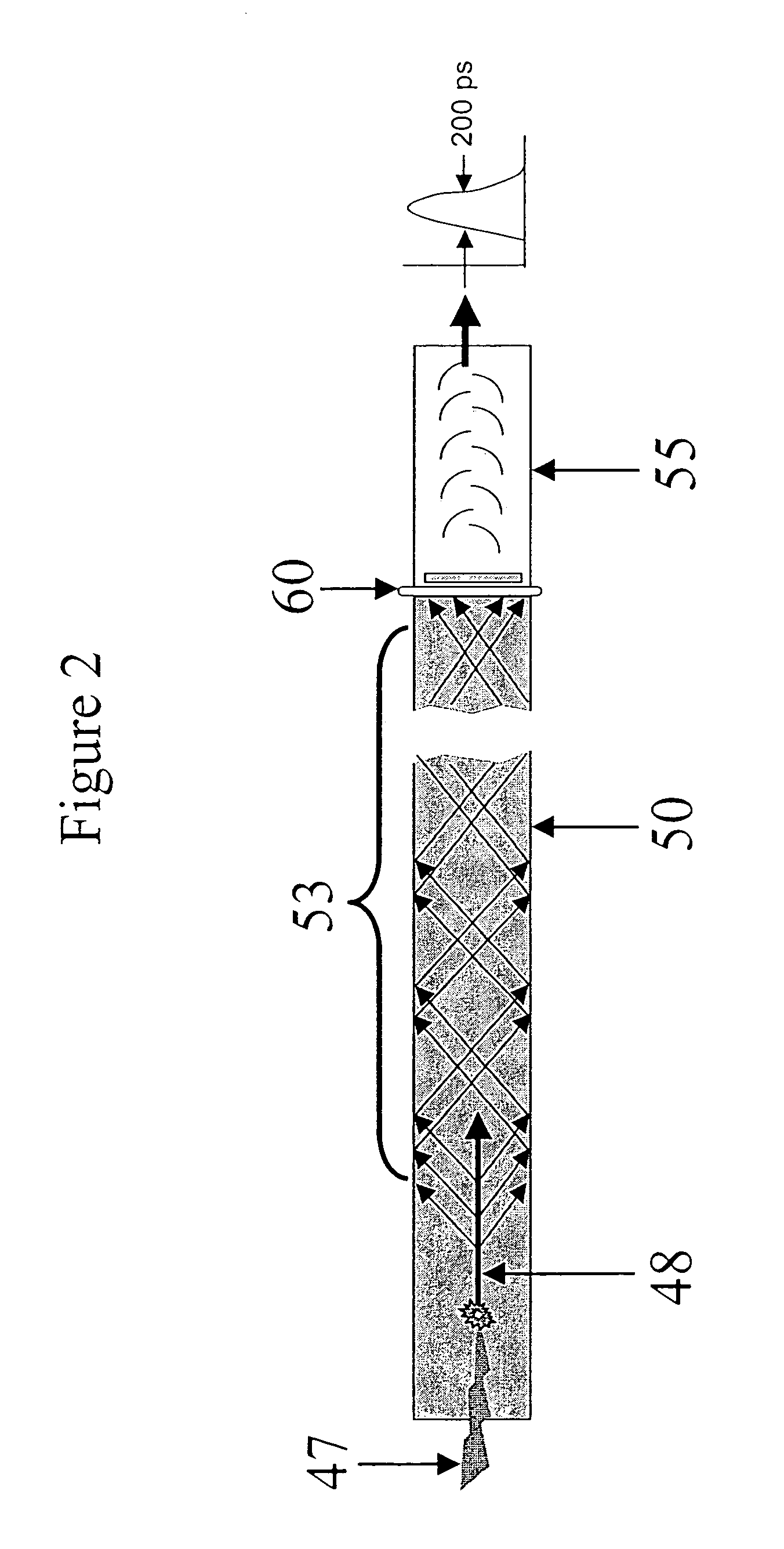
[0013]Further to the first non-limiting embodiment, the first and second detectors may be physically distinct devices or two channels, a discrete photon counting channel and an integration channel, derived from a single detector. The discrete photon counting channel can furthermore be divided electronically into an unlimited number of discriminator channels to enable finer pulse height resolution of the x-ray photon interaction events.
[0014]In a variation of the first non-limiting embodiment, the radiation source is operated alternately in a dual energy mode, at approximately 5.0 MeV to 6 MeV in a first energy mode and at approximately 8 to 10 MeV in a second energy mode. The term ‘energy’ applied to the x-ray source always refers to the peak energy of the electron beam in the accelerator. The electron beam is made to impinge on a solid target producing a broad spectrum of x-ray photons referred to as a bremsstrahlung spectrum. By application of thick filters, e.g. 10 cm of solid copper, in the beam path this spectrum can be biased substantially to the higher x-ray photon energies. Such so called ‘radiation hardening’ techniques are impractical in most known systems because of the requirement for large radiation powers in the inspection beam. The accelerator x-ray source would become extremely large and expensive if 90% or more of the radiation power was consumed by an aggressive, spectrum hardening filter. The present invention embodied in the capability to operate at scanning beam radiation powers down to 0.01 Gy / min at one meter from the x-ray source allows the use of conventional linac x-ray sources with spectral hardening filters that reduce the radiation power by more than a factor of 100. A hardened radiation spectrum at both energies can substantially improve the sensitivity of the dual energy mode to the presence of high atomic number materials.

Problems solved by technology

Previously reported high energy cargo imaging systems and methods do not provide the type of photon energy discrimination that is necessary to reduce system cost, maximize imaging performance, and provide material discrimination capabilities.
Known systems and methods integrate all photon flux interacting in the scintillator which results in three important limitations.
First, known systems have no capability to reject off-axis radiation resulting from target scattering other than by the use of expensive and ineffective collimating structures.
The limited ability of previous systems and methods to reject scattered, off-axis radiation ultimately limits target penetration regardless of the available radiation power.
Second, known systems have no method for individual x-ray photon detection.
Third, known systems have no method for counting transmitted x-ray photons according to the photon energy.
Furthermore, due to the low duty cycle nature of the pulsed x-ray sources the x-ray photons arrive in short bursts at very high rates.
High rates require extremely fast detectors and electronics.
The slow scintillators, photodiodes, and integrating electronics of known systems are completely incompatible with the high speed response requirements.

Method used


Image

  • Method and system for high energy, low radiation power X-ray imaging of the contents of a target
  • Method and system for high energy, low radiation power X-ray imaging of the contents of a target
  • Method and system for high energy, low radiation power X-ray imaging of the contents of a target

Examples


first embodiment

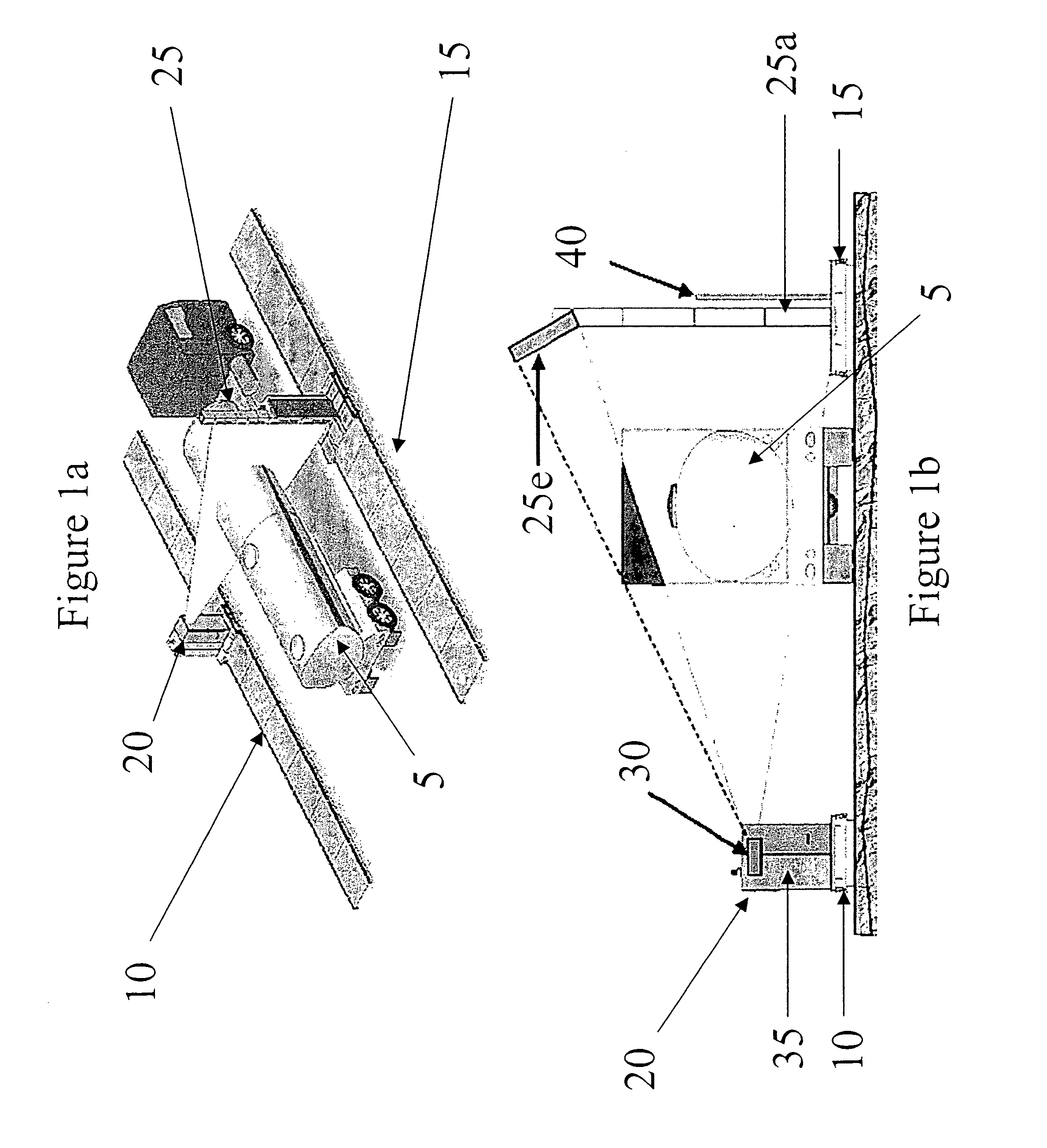
[0025]In the present invention, a relocatable dual track system is utilized as illustrated in FIGS. 1(a) and 1(b). FIG. 1(a) illustrates the basic system including a first track 10 for guiding a source 20 and a second track 15 for guiding detector component 25. The source 20 and detector component 25 are utilized in combination to image the contacts of the target 5 shown as a typical tanker truck form factor. In an alternative embodiment, the detector component 25 includes multiple detector panels 25a-X, e.g., 25a-e are shown in FIG. 1b, each of which is comprised of individual detectors, wherein detector panel 25e is angled so as to maximize detection of radiation passing through the target 5 where the target is a container cargo section as shown. With this configuration, the scan of each target is accomplished in less than 60 seconds, with throughput per hour of approximately 20-40 vehicles and scan speeds of approximately 8-12 inches per second.

[0026]Further to the first embodime...

second embodiment

[0030]In the present invention, a system and method for imaging the contents of a target includes a dual-energy, dual-imaging technique for providing data that is used to differentiate high-Z (Z stands for the average atomic number of the material by weight) materials from the low and medium Z surrounding materials. The low and medium Z materials can also be differentiated, but with less sensitivity. High-Z materials are materials with a high atomic number such as those associated with weapons of mass destruction (WMDs), e.g., material such as uranium (Z=92) and plutonium (Z=94).

[0031]Referring again to FIG. 1a, an exemplary implementation of the system includes a first track 10 for guiding a source 20 and a second track 15 for guiding detector component 25. In this second embodiment of the present invention, the source 20 is a linear accelerator (linac) operating in an interlaced mode at 5-6 MeV and 8-10 MeV end point energies. For example, linear accelerators are available from Va...

fourth embodiment

[0049]In the present invention, the target object is subjected to a follow-up inspection when a high-Z material(s) are preliminarily identified by the methods described above or by an alternative method for high-Z material identification. Once a preliminary identification of the high-Z material(s) has been made, the target object is subjected to a second scan for further analysis of the preliminarily identified material. For this second scan, the dual-energy linac described above is operated in a single mode at 9 MeV or greater. Potentially the end point energy in this scan mode could be as high as 15 MeV if this capability is built into the linac x-ray source. Neutron detectors, such as 3He pressurized detectors, bismuth germanate (BGO) scintillators, plastic scintillators, glass fiber scintillators, or any of a number of configurations using 10B, 6Li, 157Gd, B, BF3, or fission chambers can be used to detect any prompt or delayed fission neutrons resulting from the interrogation. T...


PUM

PropertyMeasurementUnit
timeaaaaaaaaaa
beam fan angleaaaaaaaaaa
thicknessaaaaaaaaaa

Abstract

The systems and methods described herein automatically detect, highlight and identify high-Z materials in volume concentrations of approximately 100 cm3 or greater utilizing single and / or dual energy sources with x-ray and neutron detectors. The methods and systems described herein are applied to the imaging of containerized cargo and cargo vehicles. Pursuant to the described systems and methods, radiation powers are orders of magnitude lower than those used in the conventional systems. By reducing the radiation power by a factor of, for example, 100 or more, the shielding requirements for the system are greatly reduced, alignment requirements can be significantly relaxed and system components can be lighter weight and more modular. Consequently, system costs are reduced.

Description

CROSS-REFERENCE TO RELATED APPLICATIONS[0001]The current application is a continuation of and claims the benefit of priority of U.S. patent application Ser. No. 11 / 070,186, filed Mar. 3, 2005 entitled METHOD AND SYSTEM FOR HIGH ENERGY, LOW RADIATION POWER X-RAY IMAGING OF THE CONTENTS OF A TARGET, which claims priority to U.S. Provisional Patent Application Ser. No. 60 / 549,671 filed Mar. 4, 2004 entitled METHOD AND SYSTEM FOR DUAL-ENERGY IMAGING OF THE CONTENTS OF A TARGET, which are incorporated herein by reference in their entirety.[0002]The U.S. Government may have a paid-up license in this invention and may have the right in limited circumstances to require the patent owner to license others on reasonable terms as provided for by the terms of contract No. N41756-04-C-4200 awarded by the Technical Support Working Group (TSWG), funded by the Department of Homeland Security.BACKGROUND OF THE INVENTION[0003]1. Field of the Invention[0004]The invention relates generally to non-intrus...

Claims


Application Information

Patent Timeline
Patent Type & Authority Patents(United States)
IPC IPC(8): G01N23/10
CPCG01V5/0041G01V5/0091G01V5/224G01V5/234G01V5/281
Inventor RICHARDSON, REX D
Owner LEIDOS
Learn More