
Adaptive frequency control apparatus and method thereof

a frequency control and frequency control technology, applied in the direction of electrial characteristics varying frequency control, pulse technique, digital transmission, etc., can solve the problems of limited frequency control range, frequency error correction at digital receiver, limitations of conventional methods proposed for frequency control, etc., to facilitate the optimization of parameters and be easy to apply

Inactive Publication Date: 2008-11-18
ELECTRONICS & TELECOMM RES INST
View PDF20 Cites 5 Cited by
  • Summary
  • Abstract
  • Description
  • Claims
  • Application Information

AI Technical Summary

Benefits of technology

Enables efficient RF frequency control across various systems, optimizing parameters and reducing development time by allowing real-time verification and flexible frequency control, ensuring optimal performance.

Problems solved by technology

But, correcting the frequency error at the digital receiver is problematic in that the frequency control range is confined according to the symbol rate.
The conventional methods proposed for the frequency control have limitations as follows.
First, the structure supporting different RF systems is not considered.
(1) When the VCO control range is 1 V for RF system A and 0.5 V for RF system B so as to have a same RF output frequency error at the antenna output, the control resolution of the RF system A is half the control resolution of the RF system B with the same control loop and algorithm of the RF system B, thus resulting in a deterioration of performance.
But this is impossible with the AFC structure designed for a specific system in the conventional methods.
Second, the conventional methods do not consider a real-time debugging for an RF controller that is necessary for the matching of the RF processor and the digital signal processor.
However, the conventional methods cannot provide such a structure, because they have AFC circuits as a black box type that shows an input-output system alone.

Method used


Image

  • Adaptive frequency control apparatus and method thereof
  • Adaptive frequency control apparatus and method thereof
  • Adaptive frequency control apparatus and method thereof

Examples


Embodiment Construction

[0035]In the following detailed description, only the preferred embodiment of the invention has been shown and described, simply by way of illustration of the best mode contemplated by the inventor(s) of carrying out the invention. As will be realized, the invention is capable of modification in various obvious respects, all without departing from the invention. Accordingly, the drawings and description are to be regarded as illustrative in nature, and not restrictive.

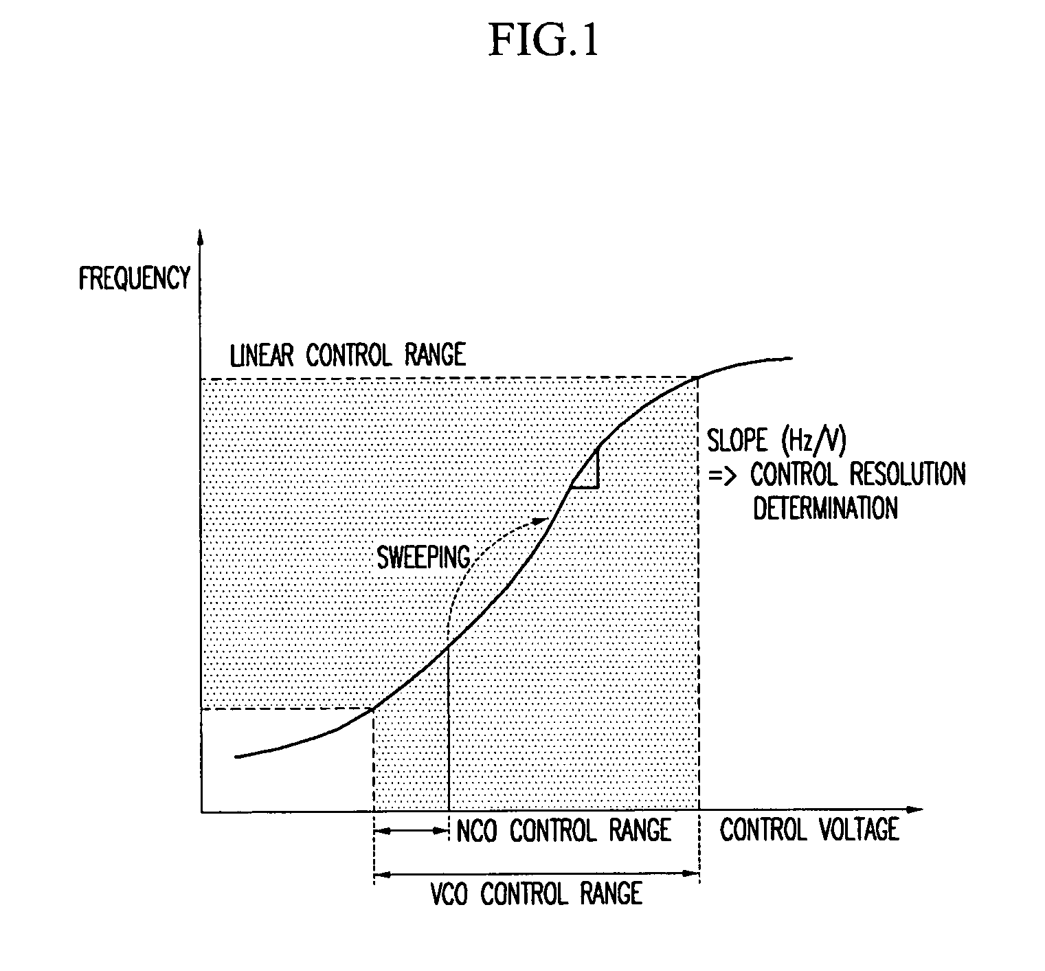
[0036]FIG. 1 is a diagram for explaining the necessity and principle of an adaptive frequency control apparatus according to the present invention.

[0037]The voltage-controlled oscillator generally used for RF frequency control has the voltage / frequency characteristic shown in FIG. 1. For the frequency control, a linear range is actually used such that the frequency value varies linearly with respect to an input voltage value. With a large slope of the linear curve, small changes in the control voltage induce significan...


PUM


Abstract

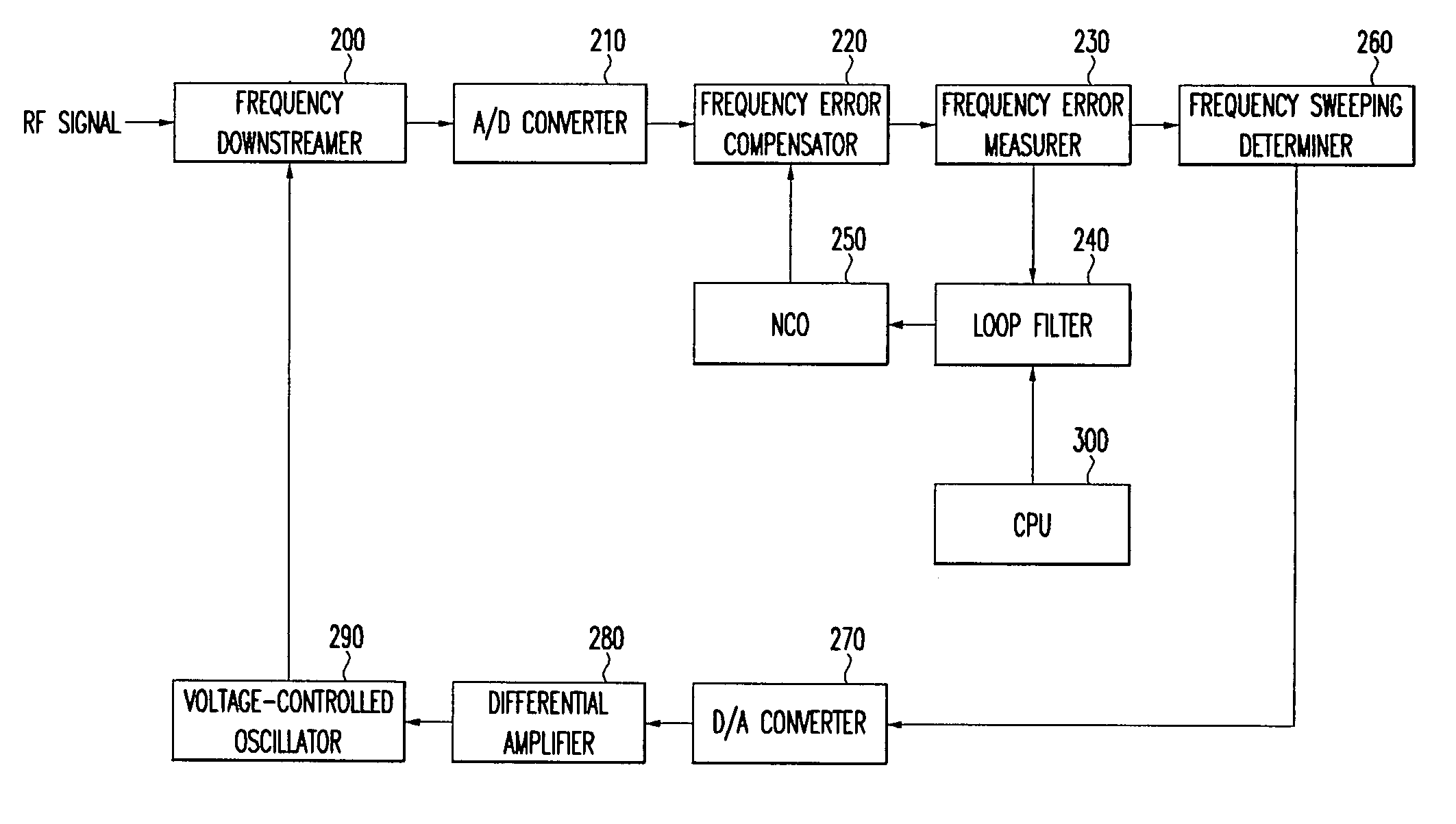
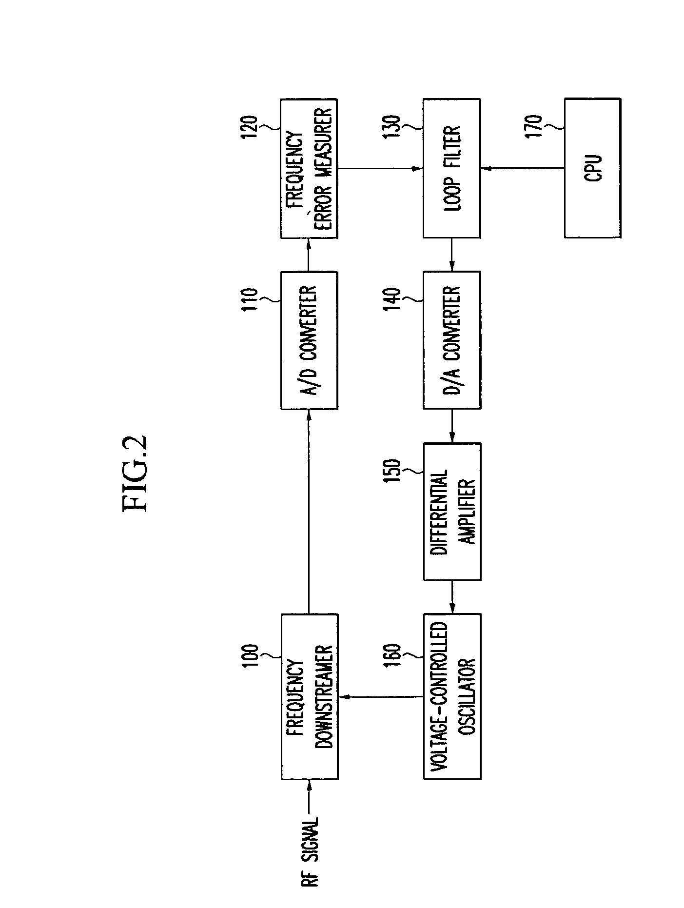
The adaptive frequency control apparatus includes: a frequency downstreamer for converting the frequency of the radio frequency signal to a frequency of a defined band according to a reference signal; a frequency error measurer for measuring a frequency error between a frequency of the output signal of the frequency downstreamer and a defined frequency; a loop filter for filtering the frequency error output from the frequency error measurer based on a plurality of operational parameters, the operational parameters being changeable; a differential amplifier for generating a control signal for a voltage control based on the output signal of the loop filter; and a voltage-controlled oscillator for changing the frequency of the reference signal according to the control signal of the differential amplifier.

Description

CROSS REFERENCE TO RELATED APPLICATION[0001]This application claims priority to and the benefit of Korea Patent Application No. 2003-98218 filed on Dec. 27, 2003 in the Korean Intellectual Property Office, the content of which is incorporated herein by reference.BACKGROUND OF THE INVENTION[0002](a) Field of the Invention[0003]The present invention relates to an adaptive frequency control apparatus and a method thereof. More specifically, the present invention relates to an adaptive frequency control apparatus and a method thereof that are necessary for the integration of radio frequency (RF) devices of different digital communication systems and a digital signal processor.[0004](b) Description of the Related Art[0005]In digital communication, especially digital mobile communication systems, RF frequency control is an important factor that determines system performance. RF frequency control between a base station and a terminal of the digital mobile communication system is needed for...

Claims


Application Information

Patent Timeline
Patent Type & Authority Patents(United States)
IPC IPC(8): H04L27/06H04B7/26H03J7/04H04K1/02
CPCH03J7/04H04B7/26
Inventor LEE, SEUNG-HWANKIM, JIN-UP
Owner ELECTRONICS & TELECOMM RES INST
Learn More