
Apparatus and method for two micro-operation flow using source override

a micro-operation and source override technology, applied in the field of integrated circuit and computer system design, to achieve the effect of improving efficiency and optimizing performan

Inactive Publication Date: 2008-11-11
INTEL CORP
View PDF5 Cites 6 Cited by
  • Summary
  • Abstract
  • Description
  • Claims
  • Application Information

AI Technical Summary

Benefits of technology

[0004]As such, these micro-operations are provided to out-of-order (OOO) logic, along with a sequence number assigned to each micro-operation. The OOO logic has several buffers that it uses to sort and reorder the flow of instructions to optimize performance as instructions go down the pipeline and get scheduled for execution. This OOO logic allows program instructions to proceed around the delayed instructions as long as they do not depend on those delayed instructions. As a result, micro-operation do not stall when following delayed instructions, in which case, efficiency dictates that the instructions execute in an out-of-order fashion.
[0005]The Dynamic Execution logic generally includes retirement logic that reorders the instructions, executed in an out-of-order fashion (dynamic manner), back into the original program order. As a result, the OOO logic generates a pool of active micro-operations that can be executed in a manner which is more efficient than conventional systems. However, in order to implement out-of-order execution, register allocation and renaming logic is required to allocate physical register to logical destination registers and rename logical source registers into physical registers in order to utilize physical register files. In addition, the allocation and renaming logic is required for execution of legacy instructions with improved efficiency.

Problems solved by technology

Unfortunately for some instructions from the SSE / SSE2 ISAs, a problem arises when the source and destination are the same and a copy of the original source is required to service the second destination.
This problem arises since the two uOP implementation does not preserve the atomicity of the original instruction.

Method used


Image

  • Apparatus and method for two micro-operation flow using source override
  • Apparatus and method for two micro-operation flow using source override
  • Apparatus and method for two micro-operation flow using source override

Examples


Embodiment Construction

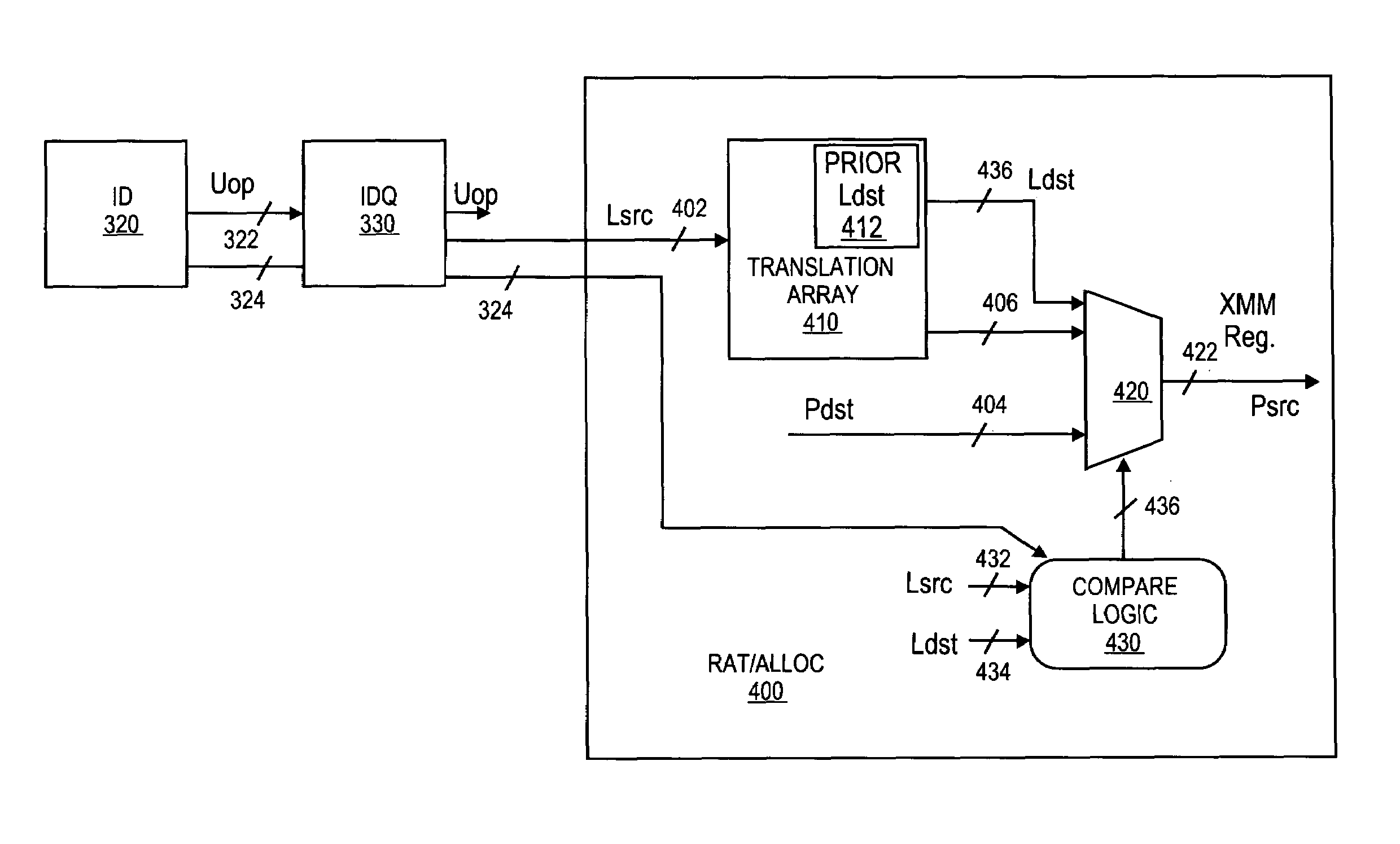
[0019]A method and apparatus for a two micro-operation flow with disabled mutual source override are described. In one embodiment, the method includes the identification of a macro-instruction having one or more streaming single instruction multiple data extension data type operands. Once received, the macro-instruction is decoded into a first micro-operation (uOP) and a second uOP. Once decoded, a signal is asserted to disable mutual source operand override logic if the first uOP updates a logical destination register that matches a logical source register of the second uOP. Otherwise, the mutual source override is active and executed by a register alias table (RAT) when uOPs with source matching source and destination are detected. In doing so, macro-instructions having 128-bit operands may be processed using, for example, two uOPs (one for the lower half and one for the upper half) in a 64-bit implementation, while preserving the atomicity of the original instruction.

[0020]In the...


PUM


Abstract

A method and apparatus for a two micro-operation flow using source override. In one embodiment, the method includes the identification of a macro-instruction having one or more streaming single instruction multiple data extension type operands. Once received, the macro-instruction is decoded into a first micro-operation (uOP) and a second uOP. Once decoded, a signal is asserted to disable source operand override logic if the first micro-operation updates a logical destination register that matches a logical source register of the micro-operation. Otherwise, the mutual source override is active and executed by a register alias table (RAT) when uOP with matching logic source and destination register are detected in a same clock cycle. In doing so, macro-instructions having 128-bit operands may be processed using, for example, two uOPs (one for the lower half and one for the upper half) in a 64-bit implementation, while preserving the atomicity of the original instruction.

Description

FIELD OF THE INVENTION[0001]One or more embodiments of the invention relate generally to the field of integrated circuit and computer system design. More particularly, one or more of the embodiments of the invention relate to a method and apparatus for two micro-operation flow using source override.BACKGROUND OF THE INVENTION[0002]Internet audio and video streaming, as well as image processing and video content creation are continuously driving system architects to design even faster microprocessors. To improve microprocessor performance, several techniques are utilized to improve the efficiency of modern day processors. One such technique for providing more efficient microprocessors is “Dynamic Execution”. In summary, Dynamic Execution functions by determining the most efficient manner for executing program instructions, irrespective of the order in which the program instructions are received.[0003]Dynamic Execution utilizes front-end logic that fetches the next instructions within...

Claims


Application Information

Patent Timeline
Patent Type & Authority Patents(United States)
IPC IPC(8): G06F9/30G06F9/318G06F9/38
CPCG06F9/30036G06F9/3824G06F9/3836G06F9/3857G06F9/3017G06F9/3855G06F9/384G06F9/30181G06F9/30145
Inventor SPERBER, ZEEVBUSTAN, YUVALVALENTINE, ROBERT
Owner INTEL CORP
Learn More