Remote interface for a network device in the physical plant

a network device and physical plant technology, applied in data switching networks, instruments, frequency-division multiplexes, etc., can solve the problems of difficult or uncomfortable access to the network device in the physical plant, preventing a service provider from providing dsl service, etc., to achieve convenient deployment of wireless network access points and greater flexibility

Inactive Publication Date: 2008-11-11
RPX CLEARINGHOUSE
View PDF15 Cites 7 Cited by
  • Summary
  • Abstract
  • Description
  • Claims
  • Application Information

AI Technical Summary

Benefits of technology

[0013]The wireless link may be formed via any convenient technology, such as one of the IEEE (Institute of Electrical and Electronics Engineers) 802.11 technologies, other wireless technology, Infrared Data Association (IrDA)-based technology or other infra-red based technology, or ultrasonic-based technologies. Infra-red and ultrasonic transmissions may be advantageous in certain applications, such as where the network device is submerged in a manhole filled with water or other fluids. 802.11-based technologies and other wireless technologies are advantageous in certain applications as they do not rely on line-of sight communications and thus may allow the technician greater flexibility in selecting a convenient site from which to interface with the network device.
[0014]According to another embodiment of the invention, the wireless transceiver may be accessed by wireless subscribers when not being used by the technician to interface with the network device. Where the wireless technology used to interface with the network device is based on 802.11 or another commonly used wireless networking technology, it is possible to enable the network device to act as an 802.11 hot spot or other network access point thus allowing for the convenient deployment of wireless network access points in the physical plant. The network device deployed in the physical plant may be configured to receive power from the central office over existing copper facilities such as one or more existing subscriber loops. According to an embodiment of the invention, the existing copper facilities may be utilized to allow the network device to be accessed remotely from the central office to enable the central office to perform various maintenance and control operations on the network device, such as to allow the network device to participate in-physical layer testing of the optical fiber connecting the central office and the network device and to enable the continuation of emergency services during the network outage.

Problems solved by technology

Technical limitations associated with DSL may prevent a service provider from providing DSL service to a subscriber residing more than a predetermined distance from the central office.
Unfortunately,. device placement and weather conditions may make it difficult or uncomfortable to access the network device in the physical plant.

Method used


Image

  • Remote interface for a network device in the physical plant
  • Remote interface for a network device in the physical plant
  • Remote interface for a network device in the physical plant

Examples


Embodiment Construction

[0022]The following detailed description sets forth numerous specific details to provide a thorough understanding of the invention. However, those skilled in the art will appreciate that the invention may be practiced without these specific details. In other instances, well-known methods, procedures, components, protocols, algorithms, and circuits have not been described in detail so as not to obscure the invention.

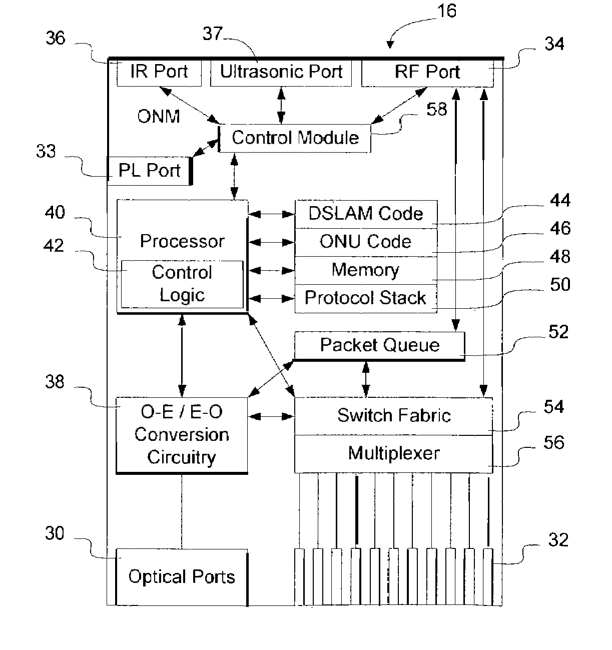
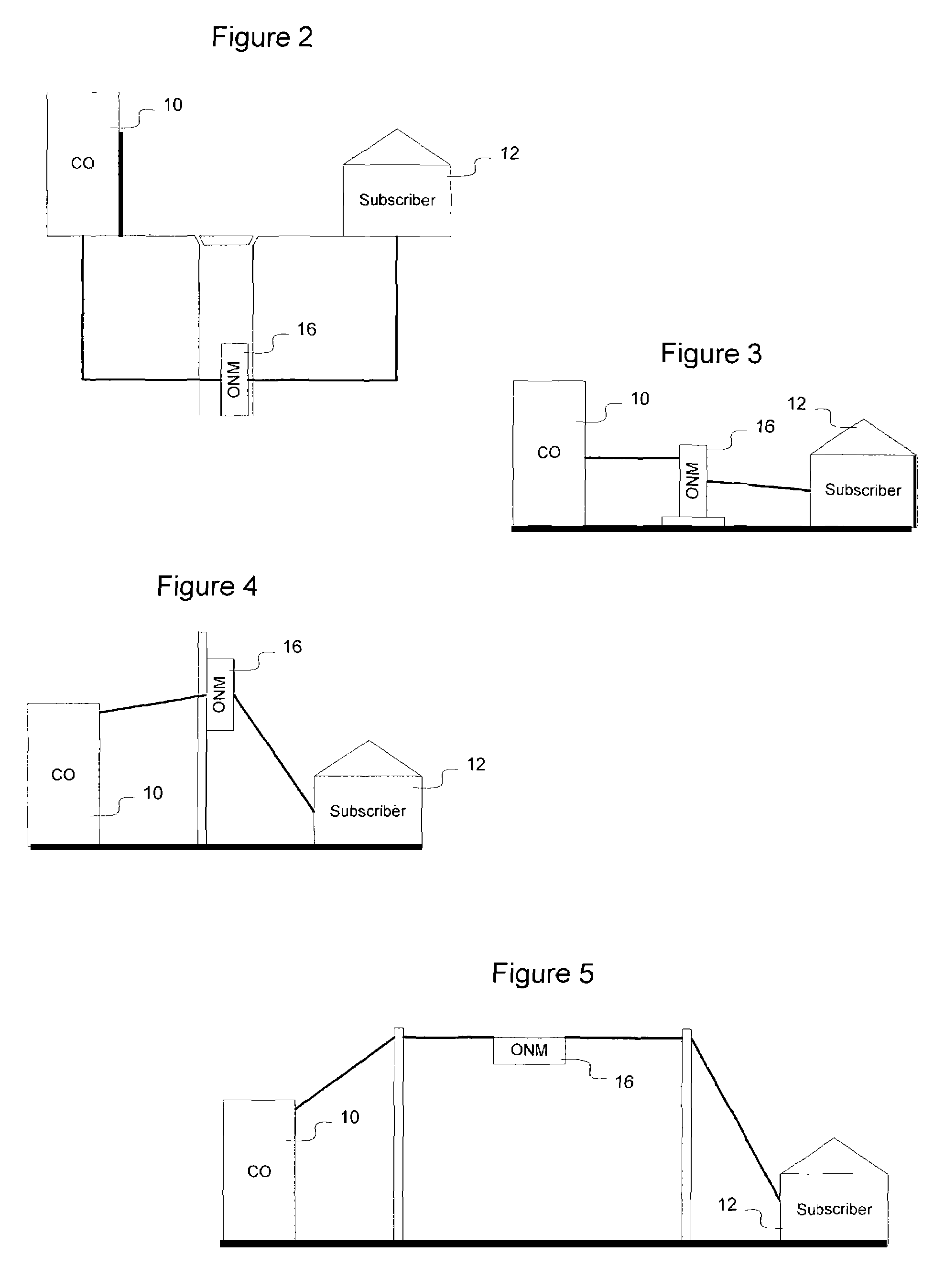
[0023]As described in greater detail below, according to an embodiment of the invention, a network device deployed in the physical plant includes a wireless access port to enable the network device to be accessed by a control unit. Enabling the network device to be accessed by a control unit enables a technician servicing the network device to monitor or perform functions on the network device remotely. Thus, where the network device is suspended above the ground, the network technician may stay safely on the ground while performing device and network diagnostics, upgrade...


PUM


Abstract

A network device such as a combination ONU-DSLAM deployed outside the central office includes a wireless transceiver to enable a technician to interface with the network device over a wireless control channel. This allows the technician to monitor, interrogate, and control the network device to ascertain performance of the network or the network device and cause the network device to perform particular desired operations. Additionally, providing a wireless interface enables the network technician to fix specific perceived problems in the network device, such as by uploading new software to the network device, to enable the network device to have increased functionality or more reliable performance. Infra-red, wireless, powerline, or another technology may be used to interface with the network device. The wireless access port may also enable subscribers to access the network, for example by causing the network device to act as an 802.11 hot spot.

Description

BACKGROUND OF THE INVENTION[0001]1. Field of the Invention[0002]The present invention relates to network equipment deployed in the physical plant and, more particularly, to a method and apparatus for remotely interfacing a network device in the physical plant.[0003]2. Description of the Related Art[0004]Data communication networks may include various computers, servers, nodes, routers, switches, hubs, proxies, and other devices coupled to and configured to pass data to one another. These devices will be referred to herein as “network devices.” Data is communicated through the data communication network by passing data packets (or cells, frames, or segments) between the network devices by utilizing one or more communication links. A particular packet may be handled by multiple network devices and cross multiple communication links as it travels between its source and its destination over the network.[0005]Many individual subscribers access the public communications network over twist...

Claims


Application Information

Patent Timeline
Patent Type & Authority Patents(United States)
IPC IPC(8): H04L12/26H04Q7/20H04L12/28H04L12/56H04W88/00
CPCH04W88/00
Inventor BERNIER, ERICWATKINS, JOHNALGIE, GLENN
Owner RPX CLEARINGHOUSE
Why Eureka
Try Eureka