Low power driver circuit for a polarization scrambler

a driver circuit and scrambler technology, applied in pulse train generators, instruments, pulse techniques, etc., can solve the problems of high power consumption of driver circuits, incompatible with standard telecom equipment practice, and polarization mode dispersion (pmd) limiting data transfer capacity, etc., to achieve low power consumption and high flexibility.

Inactive Publication Date: 2008-11-11
WSOU INVESTMENTS LLC
View PDF9 Cites 0 Cited by
  • Summary
  • Abstract
  • Description
  • Claims
  • Application Information

AI Technical Summary

Benefits of technology

[0013]Power needed for polarization scrambling is thus reduced to (low) parasitic switching and matching losses in the signal generator resp. the pulse source and in the passive filter and matching circuits, plus power consumed in the electrodes themselves, e.g. due to parasitic electro-acoustic effects and to heat generated in the ohmic resistance of the electrodes. For this reason, by means of the inventive driver circuit, polarization scrambling is an economic approach for mitigation of PMD in optical transmission.
[0020]In a further development of this embodiment, the passive filter and matching circuit of each section comprises means for adjusting the phases and / or the amplitude levels and / or the DC biases of each electrode of the section separately. This grants a high flexibility for the driving signals of the electrodes of one section.

Problems solved by technology

In optical transmission systems, in particular optical data networks, polarization mode dispersion (PMD) limits the data transfer capacity.
These driver circuits consume high power, incompatible with standard telecom equipment practice.
The driver amplifiers also generate significant heat, beyond the limits of standard telecom equipment practice.

Method used


Image

  • Low power driver circuit for a polarization scrambler
  • Low power driver circuit for a polarization scrambler
  • Low power driver circuit for a polarization scrambler

Examples


Embodiment Construction

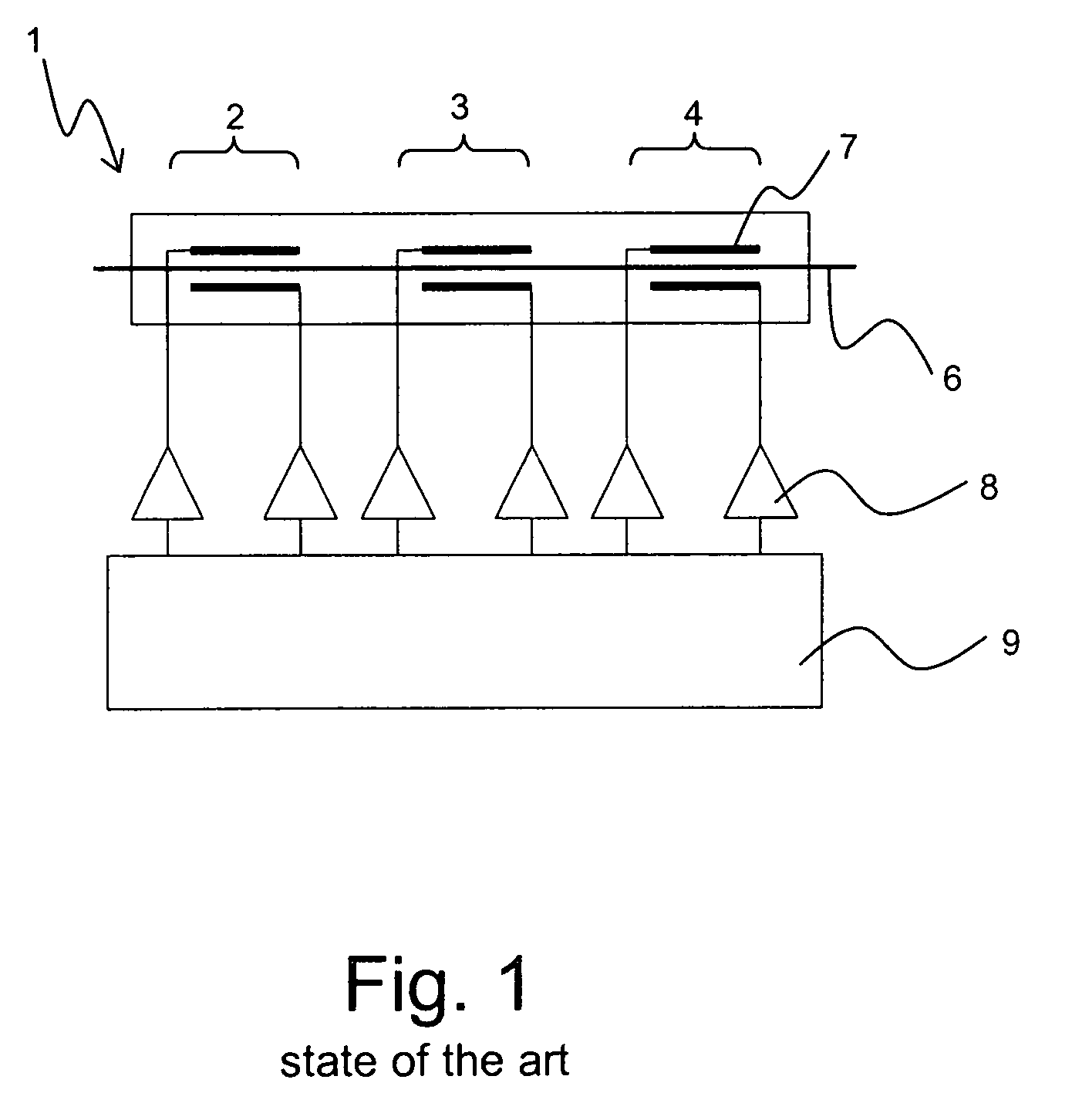
[0027]FIG. 1 shows a schematic of a polarization scrambler 1 with a driver circuit of the state of the art, i.e. a conventional broadband linear driver amplifier approach. The polarization scrambler 1 is designed as a 3-section LiNbO polarization modulator, with the three sections 2, 3, 4. Within the polarization scrambler 1, there is an optical waveguide 6. Within each section 2, 3, 4, two electrodes 7 act upon the waveguide 6 and an optical signal carried within the optical waveguide 6. The electrodes 7 apply a sinusoidal voltage to the waveguide 6, with a peak to peak amplitude of up to 70 Volts. The sections 2, 3, 4 operate at 10 MHz, 20 MHz and 30 MHz, respectively.

[0028]These sinusoidal voltages are supplied by class A amplifiers 8. For each electrode 7, one amplifier 8 is provided. The amplifiers 8 receive low level drive signals to be amplified from a driving signal generator 9. The amplifiers 8 operate in their linear regime commonly referred to as class A, supplying output...


PUM

PropertyMeasurementUnit
frequencyaaaaaaaaaa
frequencyaaaaaaaaaa
frequenciesaaaaaaaaaa

Abstract

A driver circuit for a polarization scrambler (11) having a number of electrodes (17) is characterized in that the driver circuit comprises at least one pulse source (18) emitting a pulsed signal at a fundamental frequency, that the driver circuit further comprises a plurality of passive filter and matching circuits (19) for said number of electrodes (17) of said polarization scrambler (11), wherein each passive filter and matching circuit (19) is designed for driving one or several of the electrodes (17), and wherein each passive filter and matching circuit (19) is designed such that it filters out at least one harmonic mode frequency of said pulsed signal. The inventive driver circuit has a low power consumption and generates only few heat.

Description

[0001]The invention is based on a priority application EP 05290847.2 which is hereby incorporated by reference.[0002]1. Field of the Invention[0003]The invention relates to a driver circuit for a polarization scrambler having a number of electrodes.[0004]2. Background of the Invention[0005]Such a driver circuit is used with the commercially available polarization controller type PC -A3-00-SM-FU-S-FU, distributed by EOSPACE Inc., Redmond, Wash. 98052, USA.[0006]In optical transmission systems, in particular optical data networks, polarization mode dispersion (PMD) limits the data transfer capacity. Therefore, it is useful to mitigate PMD in order to keep the line bit error rate (BER) low.[0007]One approach to mitigate PMD is polarization scrambling. The polarization is scrambled in order to cover the Poincaré sphere on an adequate trajectory within an optical transmission line for any arbitrary input polarization state.[0008]Polarization scramblers of the state of the art consist of ...

Claims


Application Information

Patent Timeline
Patent Type & Authority Patents(United States)
IPC IPC(8): G02F1/03
CPCG02F1/0136G02F1/035G02F2001/0139G02F1/0139
Inventor JUNGINGER, BERNHARD
Owner WSOU INVESTMENTS LLC
Why Eureka
Try Eureka