Method of making a low PMD optical fiber

a low-pmd, optical fiber technology, applied in the field of optical fibers, can solve the problems of pulse spreading, birefringence normally detrimental to the optical fiber performance, and disruption of the cylindrical symmetry of the fiber core, so as to reduce the birefringence, increase the fiber beat length, and reduce the effect of birefringen

Active Publication Date: 2010-09-16
PRYSMIAN SPA
View PDF11 Cites 0 Cited by
  • Summary
  • Abstract
  • Description
  • Claims
  • Application Information

AI Technical Summary

Benefits of technology

[0021]The Applicant has observed that longer beat lengths would expand the population of candidate spin functions adapted to optimize the PMD in the drawn fiber.
[0022]The Applicant has found that alternate spinning applied to a fiber reduces the fiber birefringence, and thus increases the fiber beat length. This is an unexpected result, since the general belief is that the beat length of an optical fiber is independent from the spinning process, as it depends only on the birefringence of the fiber (as stated for example in WO 2002 / 03115).
[0023]In particular, the Applicant has found that a proper choice of the parameters of a spin function applied to the fiber leads to a reduction in the birefringence, and thus to an increase in the beat length of the spun fiber, compared to birefringence, respectively the beat length, of a similar, but unspun fiber.
[0024]The increase of the fiber beat length increases the range of useful spin function periods, while fulfilling the condition that the spin period should be lower than the fiber beat length (as discussed above, the fulfillment of this condition makes the reduction in PMD achieved by applying the spin function substantially independent from the fiber beat length).
[0025]For example, it is possible to choose a longer spin period, with the advantage of not incurring in the problems of reduced spin amplitude transfer, while being reasonably sure that the condition that the spin period be lower than the fiber beat length (i.e. that the reduction in PMD achieved by applying the spin function is substantially independent from the fiber beat length) holds true for a larger population of fibers.

Problems solved by technology

However, in real-life optical fibers the cylindrical symmetry of the fiber core may be disrupted due to shape defects or non-uniform stresses.
Apart from a restricted class of fibers, known as “polarization-preserving” or “polarization-maintaining” optical fibers, in which asymmetry is deliberately introduced to generate birefringence, birefringence is normally detrimental to the optical fiber performance.
In fact, when pulsed signals are transmitted through an optical fiber, birefringence is a cause of pulse spreading, since the two polarization components, TE and TM, of the signal travel at different group velocities, and become dispersed.
Typically, the PMD phenomenon leads to a limitation of the width of the signal transmission band and, consequently, a degradation of the performance of the optical fibers along which the aforesaid signals are transmitted.
This phenomenon is therefore undesirable in systems of signal transmission along optical fibers, especially in those operating over long distances, in which it is necessary to minimize any form of attenuation or dispersion of the signals to guarantee high performances in transmission and reception.

Method used


Image

  • Method of making a low PMD optical fiber
  • Method of making a low PMD optical fiber
  • Method of making a low PMD optical fiber

Examples


Embodiment Construction

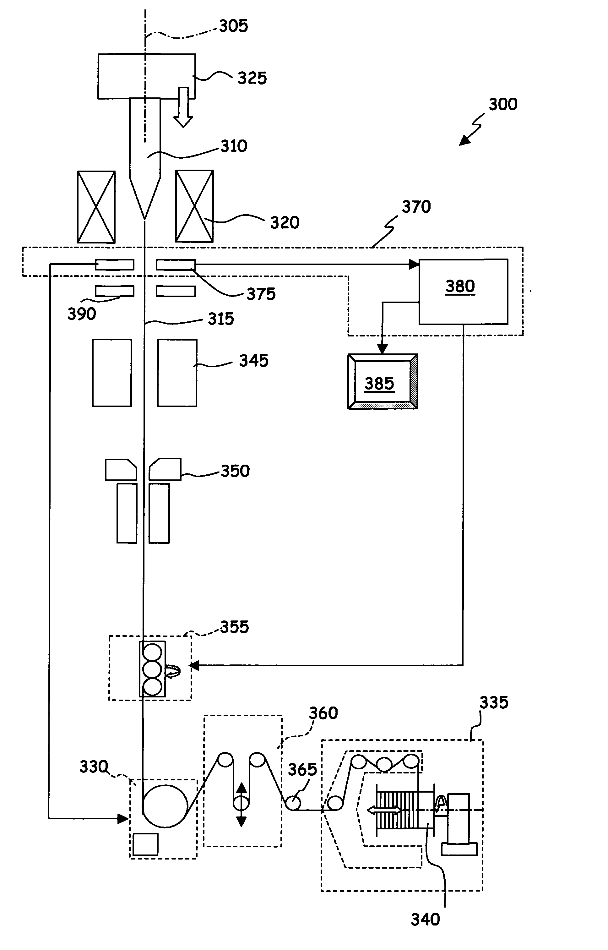
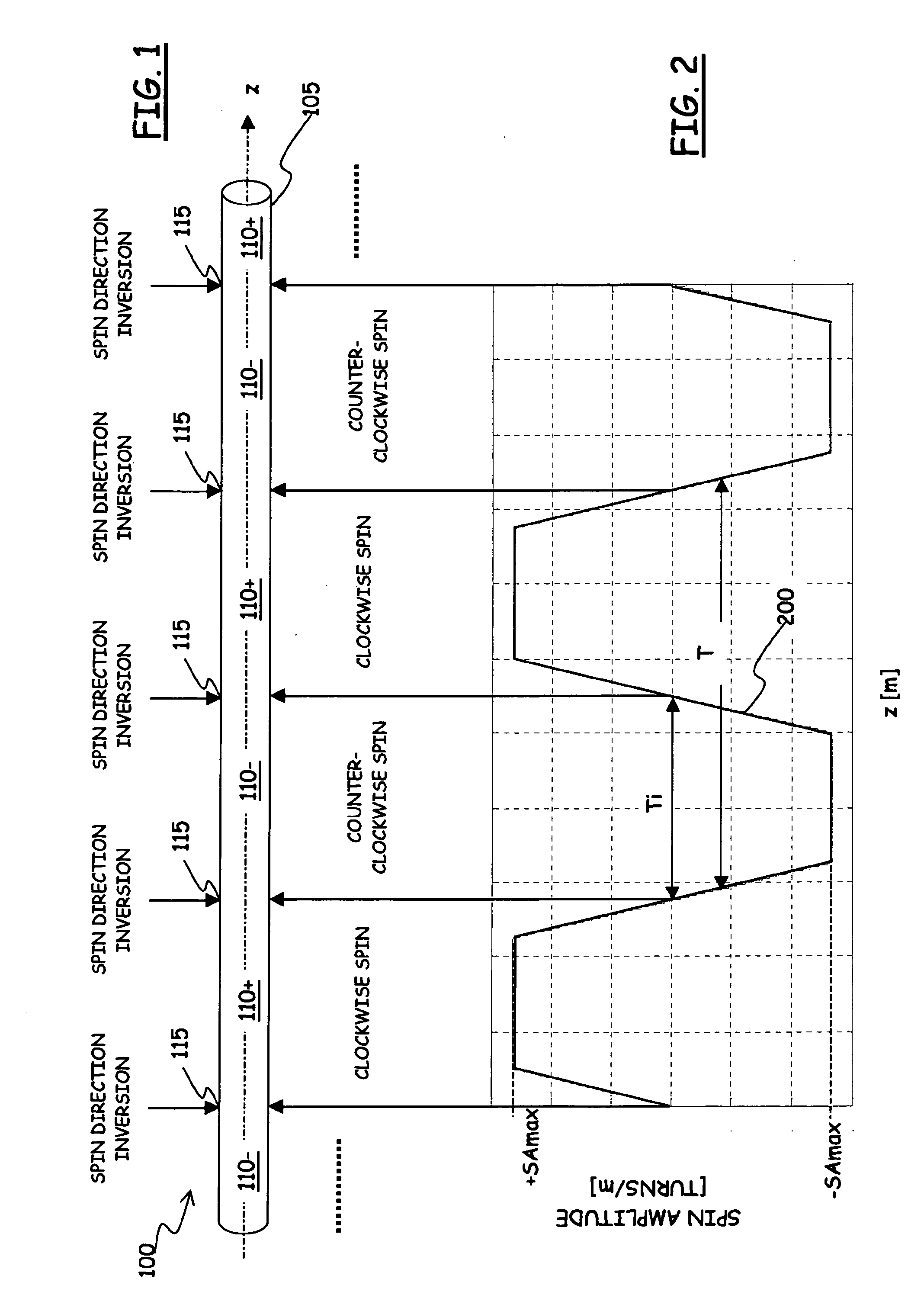
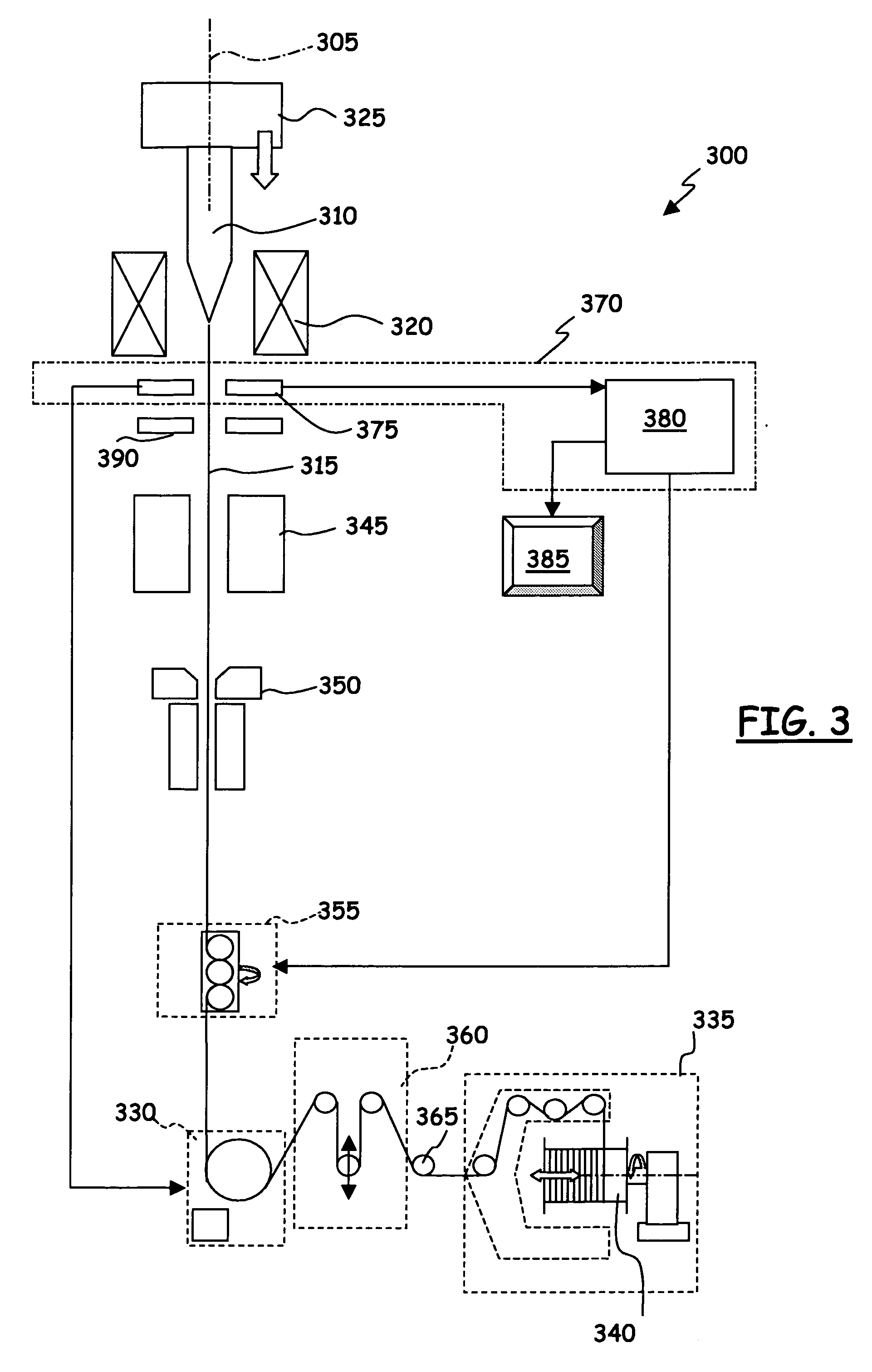
[0051]With reference to the drawings, in FIG. 1 a short section 100 of a spun optical fiber 105 is schematically shown. In particular, the fiber 105 is an alternately-spun fiber, with an alternate and, more specifically, substantially sinusoidal spin profile, in the example a trapezoidal spin profile 200, schematically depicted in FIG. 2. The spin profile 200, expressed in terms of spin amplitude (or spin rate), in turns per meter, as a function of the fiber length, taken along the z axis, in meters, is intended to represent the spin actually frozen-in in the fiber (as discussed in the following, the frozen-in spin does not coincide with the applied spin that is imparted to the fiber by a properly controlled spinning device during the fiber drawing process).

[0052]Optical fiber sub-sections 110+ and 110− are defined wherein the fiber 105 is spun, e.g., clockwise and counter-clockwise, respectively, the sub-sections 110+ and 110− being alternated to one another along the fiber axis z....


PUM

PropertyMeasurementUnit
beat lengthaaaaaaaaaa

Abstract

A method of making an optical fiber includes the steps of: providing an optical fiber preform; heating an end portion of the optical fiber preform so as to obtain a softened preform end portion; drawing the softened preform end portion to form the optical fiber; applying to the optical fiber a substantially sinusoidal spin having a spin amplitude and a spin period, the substantially sinusoidal spin being transmitted to the softened preform end portion, and determining an actual spin amplitude applied to the fiber, wherein the actual spin amplitude is the spin amplitude applied in correspondence to the softened preform end portion. The spin amplitude and spin period of the substantially sinusoidal spin are selected in such a way that a ratio of the actual spin amplitude to the spin period is in the range of approximately 0.8 to approximately 1.4 turns / m2.

Description

BACKGROUND OF THE INVENTION[0001]1. Field of the Invention[0002]The present invention generally relates to the field of optical fibers, and to manufacturing methods thereof. More particularly, the present invention concerns a method of making optical fibers featuring a low polarization mode dispersion.[0003]2. Description of the Related Art[0004]Optical signals transmitted through single-mode optical fibers comprise two orthogonal polarization modes, usually denoted Transverse Electric (TE), and Transverse Magnetic (TM). In case the fiber has a perfectly cylindrical core of uniform diameter, the two TE and TM modes propagate at a common velocity (i.e., they have same propagation constants β1=β2). However, in real-life optical fibers the cylindrical symmetry of the fiber core may be disrupted due to shape defects or non-uniform stresses. As a result, the refractive index becomes dependent on the polarization state, and the two TE and TM modes exhibit different propagation constants β...

Claims


Application Information

Patent Timeline
Patent Type & Authority Applications(United States)
IPC IPC(8): G02B6/02C03B37/02
CPCC03B37/02745C03B2203/06G02B6/02285C03B2203/36C03B2205/06C03B2203/19
Inventor SARCHI, DAVIDEFERRARIO, MADDALENA
Owner PRYSMIAN SPA
Why Eureka
Try Eureka