Anti-PMD system for optical fibers

a technology of optical fibers and pmd, applied in glass making apparatus, other domestic objects, manufacturing tools, etc., can solve the problem of optical fibers whose pmd is still too high

Active Publication Date: 2008-06-10
DRAKA COMTEQ BV
View PDF10 Cites 0 Cited by
  • Summary
  • Abstract
  • Description
  • Claims
  • Application Information

AI Technical Summary

Benefits of technology

The invention is an anti-PMD system for optical fibers that reduces its PMD (polarization mode dispersion) during drawing. It includes a pulley that alternately applies torsion torque in the clockwise and counterclockwise directions to the optical fiber. The pulley has a convex surface that comes into contact with the fiber during drawing. This system improves the quality of optical fibers and ensures better performance in applications that require high-quality optical signal transmission.

Problems solved by technology

A drawback of this prior art system is that it produces optical fibers whose PMD is still too high.

Method used


Image

  • Anti-PMD system for optical fibers
  • Anti-PMD system for optical fibers
  • Anti-PMD system for optical fibers

Examples


Embodiment Construction

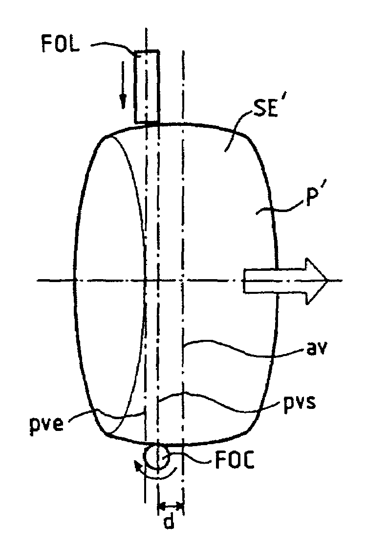
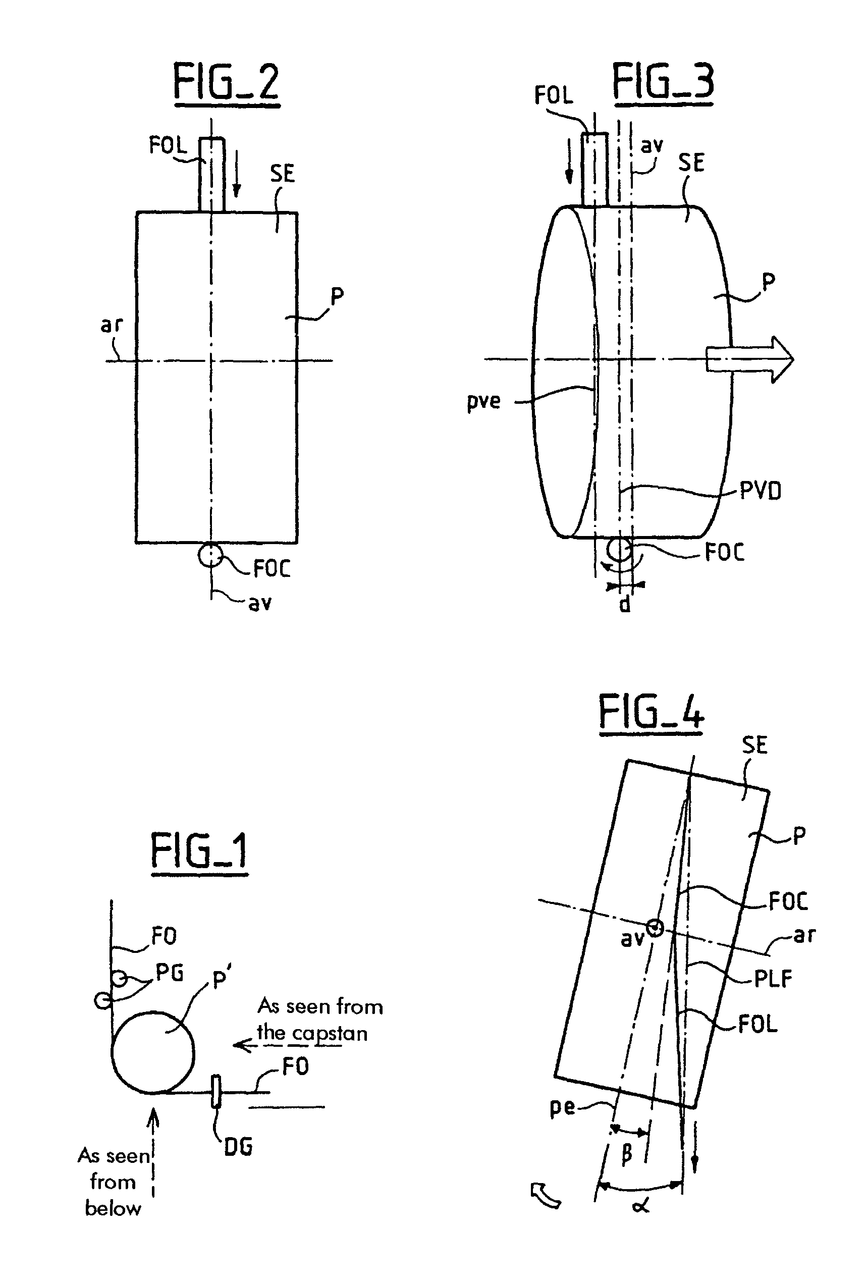
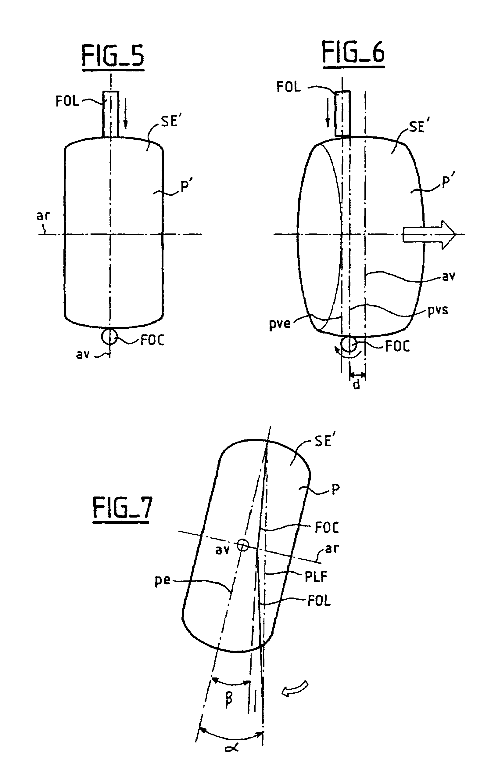
[0013]FIG. 1 shows diagrammatically a portion of a fiber drawing system for drawing an optical fiber from a preform, which portion incorporates an anti-PMD system according to the invention. FIG. 1 shows the fiber drawing system portion at the bottom of the fiber drawing tower. The optical fiber FO, which has already received its two coatings, moves in the direction of the continuous line arrows. While still moving vertically, the optical fiber FO is guided by guide pulleys PG. The optical fiber FO then changes direction on passing over the oscillating pulley P′. On leaving the oscillating pulley P′, the optical fiber FO is moving horizontally and is guided by guide fingers DG. The capstan, not shown in FIG. 1 for reasons of simplicity, is situated downstream of the guide fingers DG. Dashed line arrows show the various views used in the subsequent figures.

[0014]The various steps of fabricating the optical fiber during the fiber drawing process have a strong influence on the index ou...


PUM

PropertyMeasurementUnit
radiusaaaaaaaaaa
radiusaaaaaaaaaa
radiusaaaaaaaaaa

Abstract

An anti-PMD system comprises a pulley which oscillates in rotation and applies a torsion torque alternately in the clockwise direction and in the counterclockwise direction to an optical fiber during drawing of the optical fiber to reduce its PMD. A portion of a peripheral external surface of the pulley intended to be in contact with the optical fiber during drawing is convex.

Description

CROSS-REFERENCE TO RELATED APPLICATIONS[0001]This application is based on French Patent Application No. 02 11 128 filed Sep. 9, 2002, the disclosure of which is hereby incorporated by reference thereto in its entirety, and the priority of which is hereby claimed under 35 U.S.C. § 119.BACKGROUND OF THE INVENTION[0002]1. Field of the Invention[0003]The field of the invention is that of anti-PMD systems, the purpose of which is to reduce the polarization mode dispersion (PMD) of an optical fiber during the fiber drawing process. PMD is a problem in an optical fiber because it degrades the signal propagating in the optical fiber. This problem is becoming increasingly severe as the bit rates in optical fiber communication networks increase.[0004]2. Description of the Prior Art[0005]A prior art anti-PMD system known as the SZ system is based on the use of a flat pulley oscillating in rotation. It is described in U.S. Pat. No. 5,298,047, for example, herein incorporated by reference, and i...

Claims


Application Information

Patent Timeline
Patent Type & Authority Patents(United States)
IPC IPC(8): C03B37/022C03B37/00C03B37/03
CPCC03B37/032C03B2203/36C03B2205/06C03B2203/19
Inventor LAINET, ERICDOUGDAG, KAMELBOURHIS, JEAN-FRANCOIS
Owner DRAKA COMTEQ BV
Why Eureka
Try Eureka