


Quick Research
Generate reliable direction feasibility study reports for your R&D in just a few steps.

Technical Q&A
Discover and master advanced knowledge NOW. Basics, ideas, possibilities, all at once.

Find Solutions
As an expert in R&D theories, this can generate solutions to your technical problems instantly.

Evaluate Feasibility
Analyze your overall solution with one click, know your potential R&D risks in advance.

Monitor Landscape
Get weekly tech updates, stay abreast of the latest tech innovations and key insights.
Compressor having an oil residue pool
a technology of compressor and oil residue, which is applied in the direction of positive displacement liquid engine, transportation item, liquid fuel engine, etc., can solve the problems of lowering hardly allowing oil to reside in the oil pump, and achieve the effect of enhancing the oil supply performance of the oil pump
- Summary
- Abstract
- Description
- Claims
- Application Information
AI Technical Summary
Benefits of technology
Problems solved by technology
Method used
Image

Examples
first embodiment
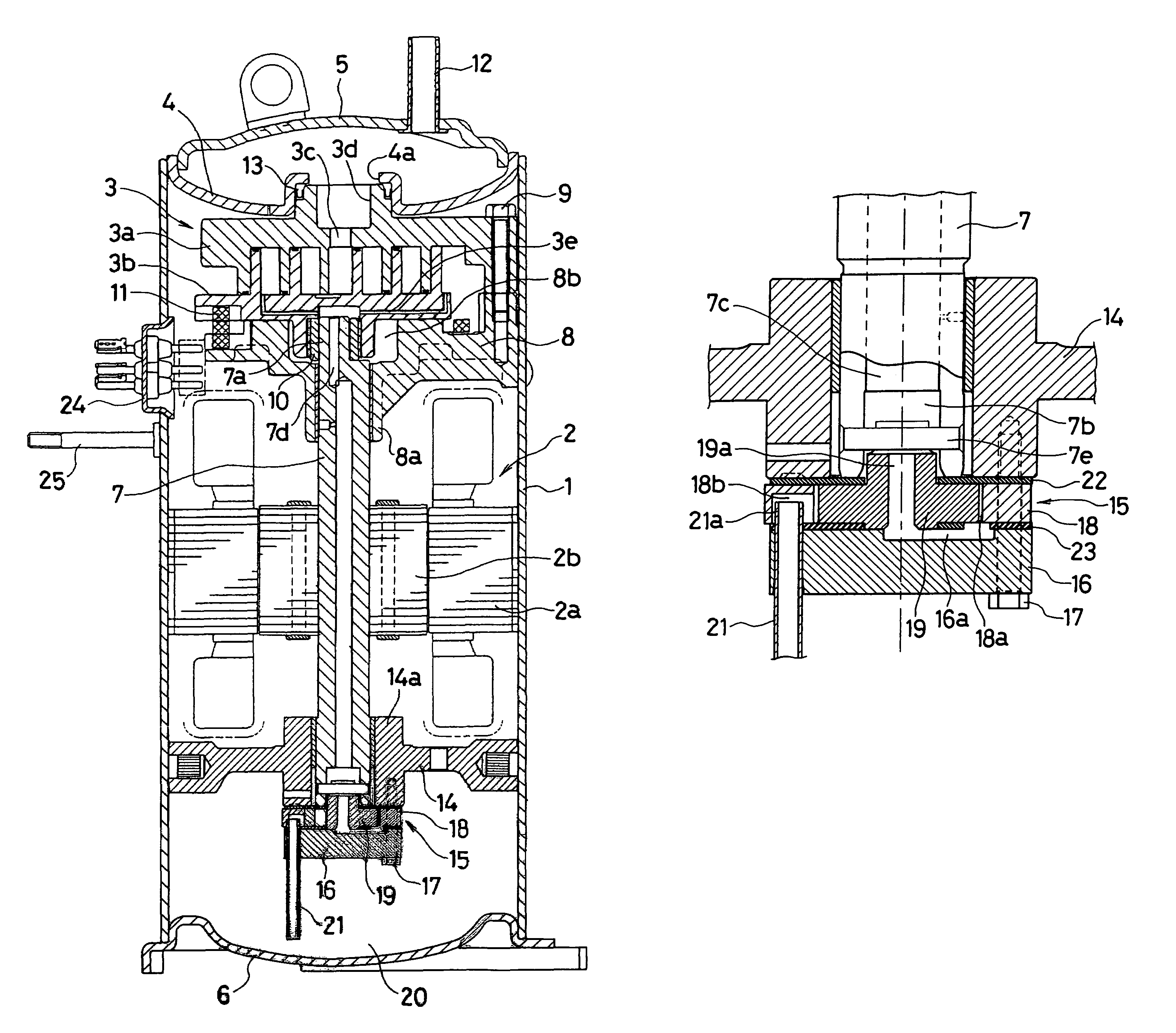
[0027]FIG. 1 is a brief vertical cross-sectional view showing the present invention. In the figure, the reference numeral 1 denotes a cylindrical container body, which houses an electric element 2 and a compressive element 3 driven by the electric element 2 as arranged in the body. An upper cap 5 is attached to the upper end of the container body 1 with a partition disc 4 interposed therebetween. A lower cap 6 is attached to the lower end of the container body 1 to configure a hermetic container.
[0028]The electric element 2 is an electric motor, which includes a stator 2a having an outer circumferential portion fixed on the inner wall of the container body 1 almost at the central portion, and a rotor 2b rotatably disposed on the central portion of the stator 2a. A drive shaft 7 is inserted through and axially installed on the central portion of the rotor 2b.
[0029]The compressive element 3 is of the publicly known scroll type, which includes a fixed scroll 3a having a swirling reces...
second embodiment
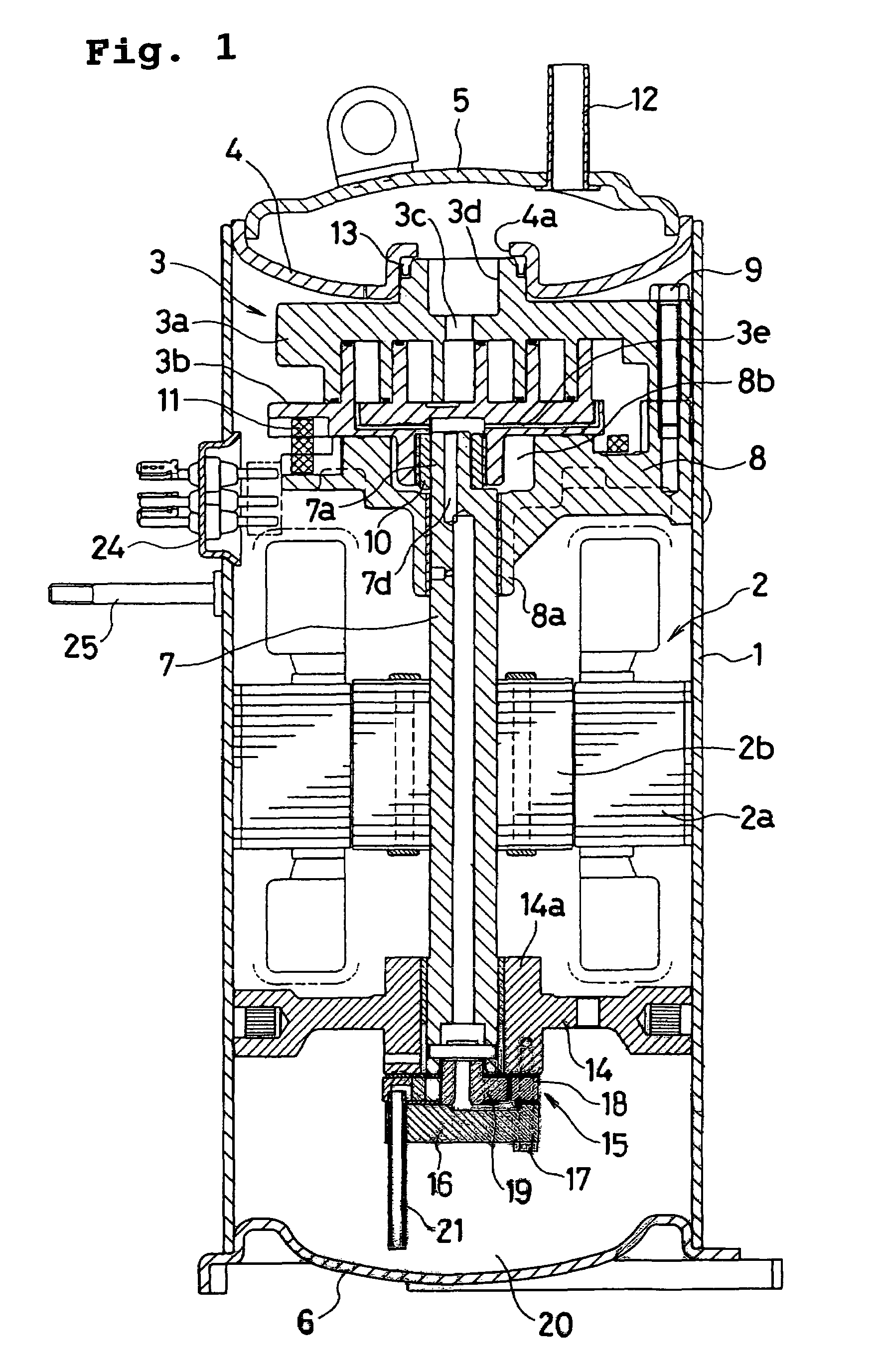
[0048]In the second embodiment, the oil sucked up from the oil storage 20 flows from the upper end of the suction pipe 21 into the communication notch 18b. It also flows through the higher oil passage 18d above the standing wall 18c into the inner space 18a of the cylinder 18. The oil led in the inner space 18a of the cylinder 18 flows through the eccentric annular oil passage, the communication path 16a of the attachment member 16 and the through bore 19a of the rotator 19 into the oil passage 7c of the driveshaft 7. The oil is then supplied from the oil supply hole provided in the oil passage 7c to the bearing portion 14a of the lower support frame 14 and the bearing portion 8a of the upper support frame 8. The oil led in the eccentric cum 7a of the driveshaft 7 is supplied to the bearing 10 portion that bears the swinging scroll 3b and to the sliding portion between the swinging scroll 3b and the upper support frame 8 to lubricate these portions sufficiently.
[0049]When power supp...
third embodiment
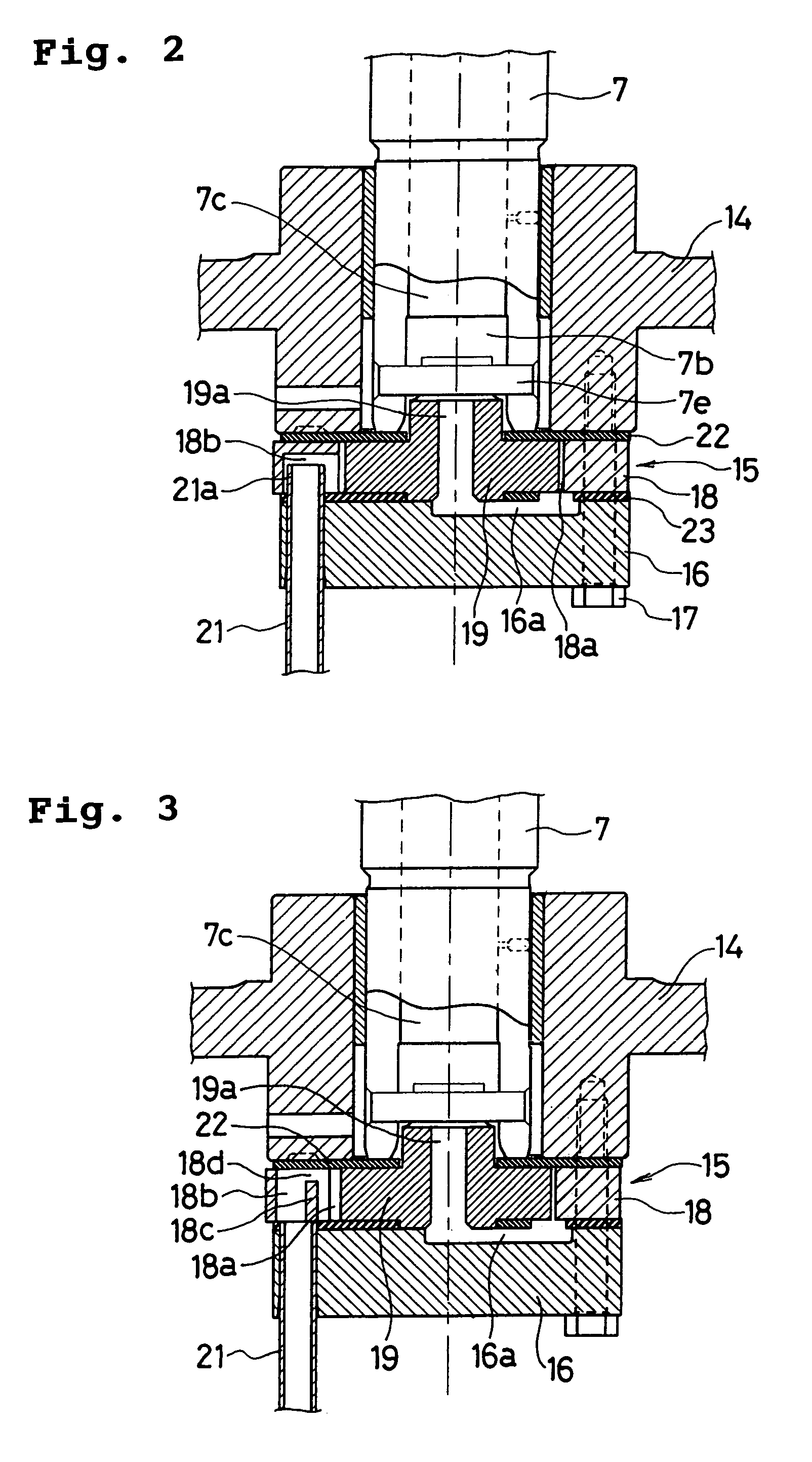
[0054]In the third embodiment, the oil sucked up from the oil storage 20 flows from the upper end of the suction pipe 21 into the communication notch 18b. It also flows through the higher oil passage 22a above the standing wall 18c into the inner space 18a of the cylinder 18. The oil led in the inner space 18a of the cylinder 18 flows through the eccentric annular oil passage, the communication path 16a of the attachment member 16 and the through bore 19a of the rotator 19 into the oil passage 7c of the driveshaft 7. The oil is then supplied from the oil supply hole provided in the oil passage 7c to the bearing portion 14a of the lower support frame 14 and the bearing portion 8a of the upper support frame 8. The oil led in the eccentric cum 7a of the driveshaft 7 is supplied to the bearing 10 portion that bears the swinging scroll 3b and to the sliding portion between the swinging scroll 3b and the upper support frame 8 to lubricate these portions sufficiently.
[0055]When power suppl...
PUM
 Abstract
Description
Claims
Application Information
 - R&D Engineer
- R&D Manager
- IP Professional
- Industry Leading Data Capabilities
- Powerful AI technology
- Patent DNA Extraction
Browse by: Latest US Patents, China's latest patents, Technical Efficacy Thesaurus, Application Domain, Technology Topic, Popular Technical Reports.
© 2024 PatSnap. All rights reserved.Legal|Privacy policy|Modern Slavery Act Transparency Statement|Sitemap|About US| Contact US: help@patsnap.com