Oil supply device for linear compressor

A technology of linear compressor and oil supply device, applied in mechanical equipment, machine/engine, liquid variable capacity machinery, etc., to achieve the effect of improving oil supply capacity

Inactive Publication Date: 2012-06-13
TECHNICAL INST OF PHYSICS & CHEMISTRY - CHINESE ACAD OF SCI
View PDF0 Cites 0 Cited by
  • Summary
  • Abstract
  • Description
  • Claims
  • Application Information

AI Technical Summary

Problems solved by technology

[0005] Linear compressors are small hermetic piston compressors, but because their motors do linear reciprocating motion, there is no rotary motion as the power of the oil pump. The above-mentioned rotary shaft in the compressor drives the oil supply device to supply oil to each friction surface. The traditional oil supply method can no longer be used

Method used


Image

  • Oil supply device for linear compressor
  • Oil supply device for linear compressor
  • Oil supply device for linear compressor

Examples


Embodiment 1

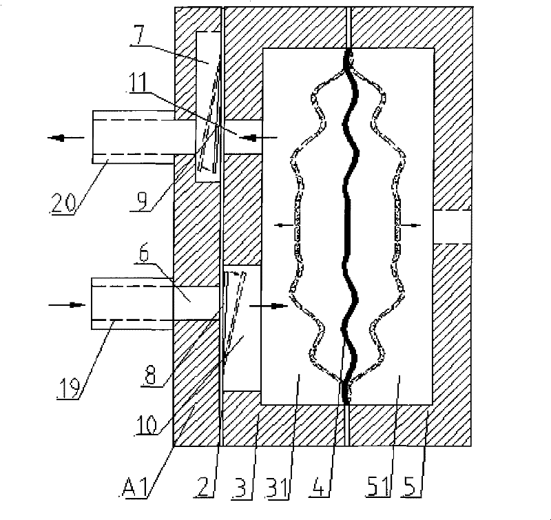
[0029] figure 1 It is a schematic diagram of the structure and principle of the linear compressor oil supply device (an embodiment) of the present invention; it can be seen from the figure that the linear compressor oil supply device provided by the present invention provided in Embodiment 1 includes:

[0030] A first groove 3 and a second groove 5 that interlock an elastic film 4 between the two; and a left end cover that covers the outer surface of the bottom of the first groove 3 A1;

[0031] The first groove 3 and the elastic membrane 4 enclose a first cavity 31; the second groove 5 and the elastic membrane 4 enclose a second cavity 51;

[0032] The bottom of the first groove 3 is provided with an oil supply through hole 11 and an oil suction through groove 10; the first end cover 1 is provided with an oil supply blind groove 7 with an open end and an oil suction through hole 6;

[0033] The oil-suction hole 6 communicates with the oil-suction groove 10; the oil-suction ...

Embodiment 2

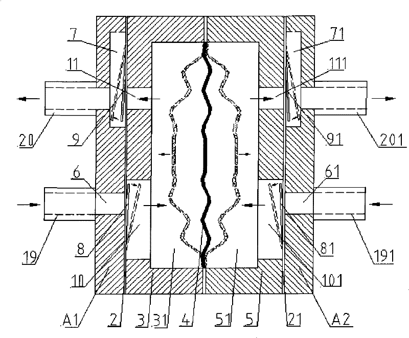
[0042] figure 2It is a schematic diagram of the structure and principle of the linear compressor oil supply device (another embodiment) of the present invention; it can be seen from the figure that the linear compressor oil supply device provided by the present invention includes the structure described in Embodiment 1 In addition, it may further include a right end cover A2 covering the outer surface of the bottom of the second groove 5;

[0043] The bottom of the second groove 5 is provided with an oil supply through hole 111 and an oil suction through groove 101; the first end cover 1 is provided with an oil supply blind groove 71 with an open end and an oil suction through hole 61;

[0044] The oil-suction through hole 61 communicates with the oil-suction through-groove 101; a one-way oil-suction valve 81 is installed on the end face of the oil-suction through-hole 61 connected with the oil-suction through-groove 101; The direction of the second cavity 51 is opened;

[...


PUM


Abstract

The invention relates to an oil supply device for a linear compressor. The oil supply device comprises first and second grooves which are buckled with each other and clamp an elastic film therebetween, and a first end cover covering on an outer surface of the bottom of the first groove; the first and second grooves and the elastic film enclose to form a first cavity and a second cavity respectively; an oil supply through hole and an oil absorption through groove are formed at the bottom of the first groove; the first end cover is provided with an oil supply blind groove and an oil absorption through hole; the oil absorption through hole is communicated with the oil absorption through groove, and an end surface where the oil absorption through hole is communicated with the oil absorption through groove is provided with a one-way oil absorption valve opened toward a direction close to the first cavity; the oil supply through hole is communicated with the oil supply blind groove, and an end surface where the oil supply through hole is communicated with the oil supply blind groove is provided with a one-way oil supply valve opened toward a direction away from the first cavity; the centre of the elastic film is connected with a moving component of the compressor or provided with a balance weight. When the linear compressor works, the elastic film reciprocates so as to change the volume of the cavity; if the volume of the cavity is larger, negative pressure is generated in the cavity, so that the oil absorption valve is opened and the oil enters the cavity; and if the volume of the cavity is smaller, the pressure in the cavity is increased, so that an oil discharge valve is opened and the oil enters a cylinder of the compressor.

Description

technical field [0001] The invention belongs to an oil supply device for a compressor in the technical field of fluid machinery and refrigeration, in particular to an oil supply device for a linear compressor. Background technique [0002] There are many ways to supply oil for compressor lubricating oil due to different models, mainly divided into two categories: splash lubrication and pressure lubrication. [0003] The principle of splash lubrication is to splash the lubricating oil in the crankcase to each friction surface by means of the oil strike rod on the connecting rod, or use the ring on the shoulder of the crankshaft journal to bring the lubricating oil in the crankcase to the surface of the main journal , and then the lubricating oil splashes to each friction surface under the action of centrifugal force. It is difficult to control the amount of oil supplied by splash lubrication, and the cooling effect on the friction surface is poor, so it is suitable for small...

Claims


Application Information

Patent Timeline
Patent Type & Authority Patents(China)
IPC IPC(8): F04B39/02
Inventor 田长青邹慧明张立钦
Owner TECHNICAL INST OF PHYSICS & CHEMISTRY - CHINESE ACAD OF SCI
Why Eureka
Try Eureka