
Perpendicular head with trailing shield and rhodium gap process

a technology of trailing shield and perpendicular head, which is applied in the manufacture of magnetic recording, and perpendicular magnetisation head surfaces, etc., can solve the problems of inability to meet the density requirements for today's storage needs, physical limitations experienced using longitudinal recording systems, and high undesirable writing to adjacent tracks

Inactive Publication Date: 2008-10-28
HITACHI GLOBAL STORAGE TECH NETHERLANDS BV
View PDF8 Cites 43 Cited by
  • Summary
  • Abstract
  • Description
  • Claims
  • Application Information

AI Technical Summary

Benefits of technology

This design prevents corner rounding, maintains accurate track alignment, and enhances data recording precision by maintaining a straight magnetic field, reducing power consumption and improving recording density.

Problems solved by technology

As the recording density of magnetic hard drives (or disk drives) increases, a physical limitation is experienced using longitudinal recording systems partly due to thermal relaxation known as super-paramagnetism.
That is, the density requirements for meeting today's storage needs are simply not attainable with longitudinal recording systems.
That is, writing to adjacent tracks is highly undesirable because it causes corruption of data on adjacent tracks.
One of the problems associated with prior art perpendicular write heads is controlling the critical gap thickness, i.e. the thickness between the top pole and the trailing shield.
Another problem associated with prior art perpendicular write heads is the alignment of the trailing shield with the main pole.
But perhaps the more severe problem therewith remains top pole damages and corner rounding caused from chemical mechanical planarization (CMP) process, such as described in further detail below.
This effect adversely impacts system performance by degrading accurate recording of data onto the disc, as well as, unnecessarily higher power consumption.

Method used


Image

  • Perpendicular head with trailing shield and rhodium gap process
  • Perpendicular head with trailing shield and rhodium gap process
  • Perpendicular head with trailing shield and rhodium gap process

Examples


Embodiment Construction

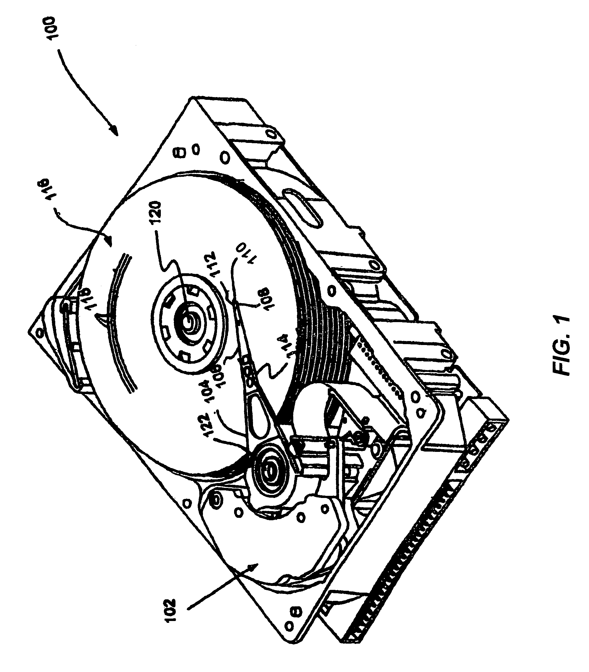
[0023]Referring now to FIG. 1, a top perspective view of a disk drive 100 is shown in accordance with an embodiment of the present invention. The disk 100 is shown to include a voice coil motor (VCM) 102, an actuator arm 104, a suspension 106, a flexure 108, a slider 110, a write (perpendicular) head 112, a head mounting block 114, and disk or media 116. Suspension 106 is connected to the actuator arm 104 at the head mounting block 114. The actuator arm 104 is coupled to the VCM 102. The disk 116 includes a plurality of tracks 118 and rotates about axis 120. The tracks 118 are circular, each extending circularly around the surface of the disk 116 for storing magnetically-encoded data or information using the perpendicular head 112, which will be discussed in greater detail with respect to further figures. The embodiments of the present invention reduce undesirable writing or programming of adjacent tracks, as will be apparent shortly.

[0024]During operation of the disk drive 100, rot...


PUM

PropertyMeasurementUnit
thicknessaaaaaaaaaa
thicknessaaaaaaaaaa
thicknessaaaaaaaaaa

Abstract

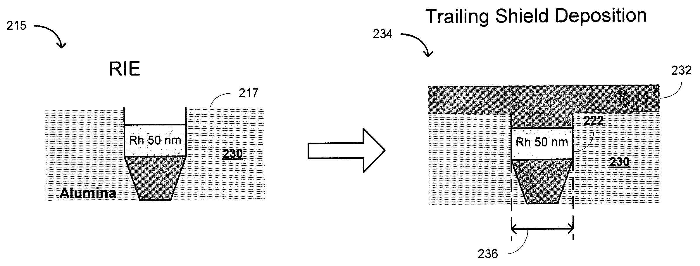
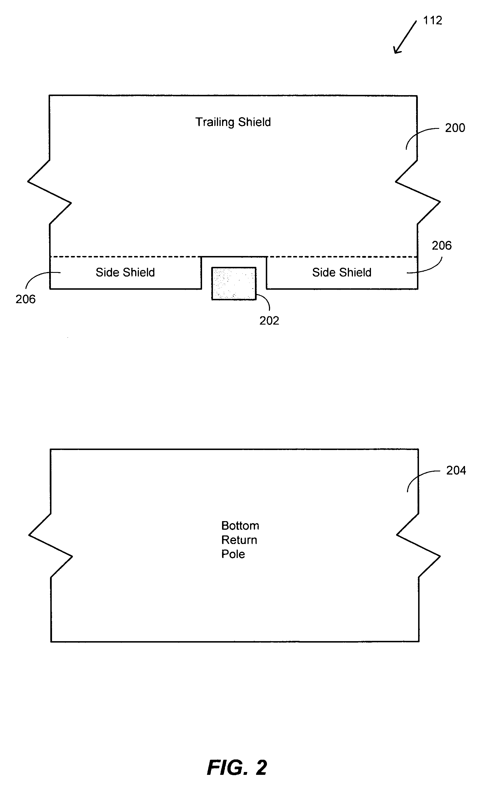
A perpendicular write head including a main pole and a trailing shield, the main pole being made of a diamond-like carbon (DLC) layer as hard mask and a rhodium (Rh) layer as shield gap, both DLC and Rh layers being CMP stop layers so as to avoid corner rounding and damage from chemical mechanical planarization (CMP) process, the DLC layer being removed by reactive ion etching (RIE) to create a trench, the trailing shield being deposited into the trench for self alignment.

Description

CROSS REFERENCE TO RELATED APPLICATIONS[0001]This application is a continuation-in-part of prior U.S. patent application Ser. No. 10 / 836,867 filed on Apr. 30, 2004 and entitled “HIGH MILLING RESISTANCE WRITE POLE FABRICATION FOR PERPENDICULAR RECORDING,” the contents of which is incorporated herein by reference as though set forth in full and related to U.S. patent application Ser. No. 11 / 195,227, filed on Aug. 1, 2005 and entitled “BILAYER TRAILING SHIELD GAP FOR PERPENDICULAR HEAD”, the contents of which is incorporated herein by reference, as though set forth in full, and related to U.S. patent application Ser. No. 11 / 195,532, filed on Aug. 1, 2005 and entitled “PERPENDICULAR WRITE POLE FORMATION USING DURIMIDE / ALUMINA HARD MASK WITHOUT CMP LIFTOFF, the contents of all of these documents are incorporated herein by reference, as though set forth in full.BACKGROUND OF THE INVENTION[0002]1. Field of the Invention[0003]This invention relates generally to the field of perpendicular ma...

Claims


Application Information

Patent Timeline
Patent Type & Authority Patents(United States)
IPC IPC(8): G11B5/127H04R31/00G11B5/187
CPCG11B5/1278G11B5/1871G11B5/3116G11B5/315G11B5/3163Y10T29/49046Y10T29/49052Y10T29/49048Y10T29/49043
Inventor GAO, YUNXIAOGUTHRIE, HUNG-CHINJIANG, MINGZHANG, SUE SIYANG
Owner HITACHI GLOBAL STORAGE TECH NETHERLANDS BV
Learn More