Fan and rotor structure thereof

a technology of rotor structure and fan, which is applied in the direction of liquid fuel engine, marine propulsion, vessel construction, etc., can solve the problems of limited shock resistance of the rotor structure, shaft and case separation in operation, and copper sheath, etc., to prolong the life of the fan, improve the anti-rust properties, and improve the effect of pressurization

Inactive Publication Date: 2008-10-21
DELTA ELECTRONICS INC
View PDF16 Cites 3 Cited by
  • Summary
  • Abstract
  • Description
  • Claims
  • Application Information

AI Technical Summary

Benefits of technology

[0008]Accordingly, the invention provides a rotor structure to increase anti-rust properties thereof and to extend the fan life. The present invention also provides a rotor structure having improved pressurization. A fan with a rotor structure with extended life can be obtained.

Problems solved by technology

In a large fan with significant size and weight, however, the shaft and the case may separate in operation due to the weight of the rotor structure.
In the conventional rotor structure 100, however, the copper sheath 106 is riveted to the case 102 by compression, so that the shock resistance of the rotor structure is limited.
Thus, due to degradation of the electrocoating layer, the case 102 and the copper sheath 106 are exposed and may rust.
In either case, the rotor structure and other elements in the fan may be damaged.

Method used


Image

  • Fan and rotor structure thereof
  • Fan and rotor structure thereof
  • Fan and rotor structure thereof

Examples


Embodiment Construction

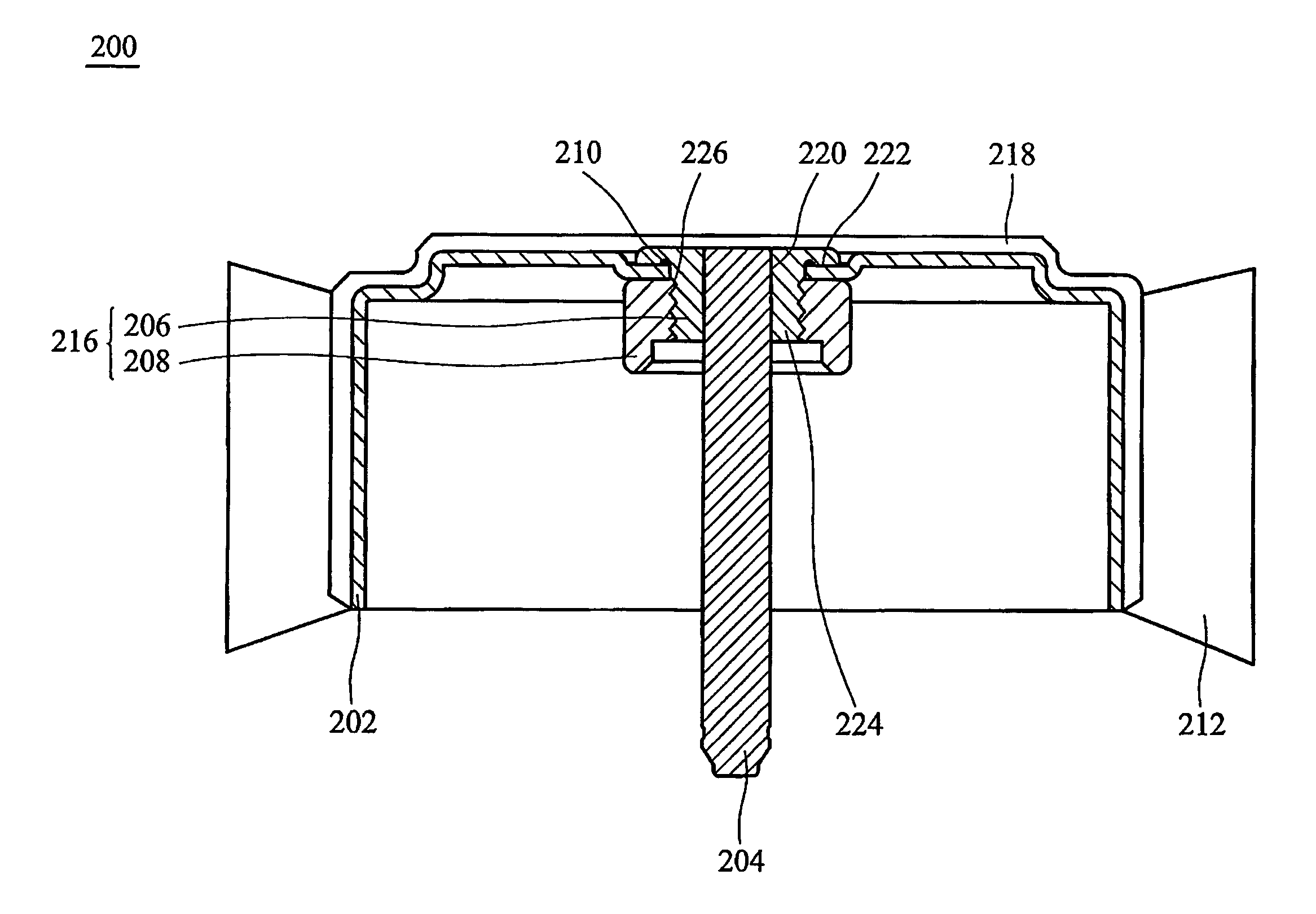
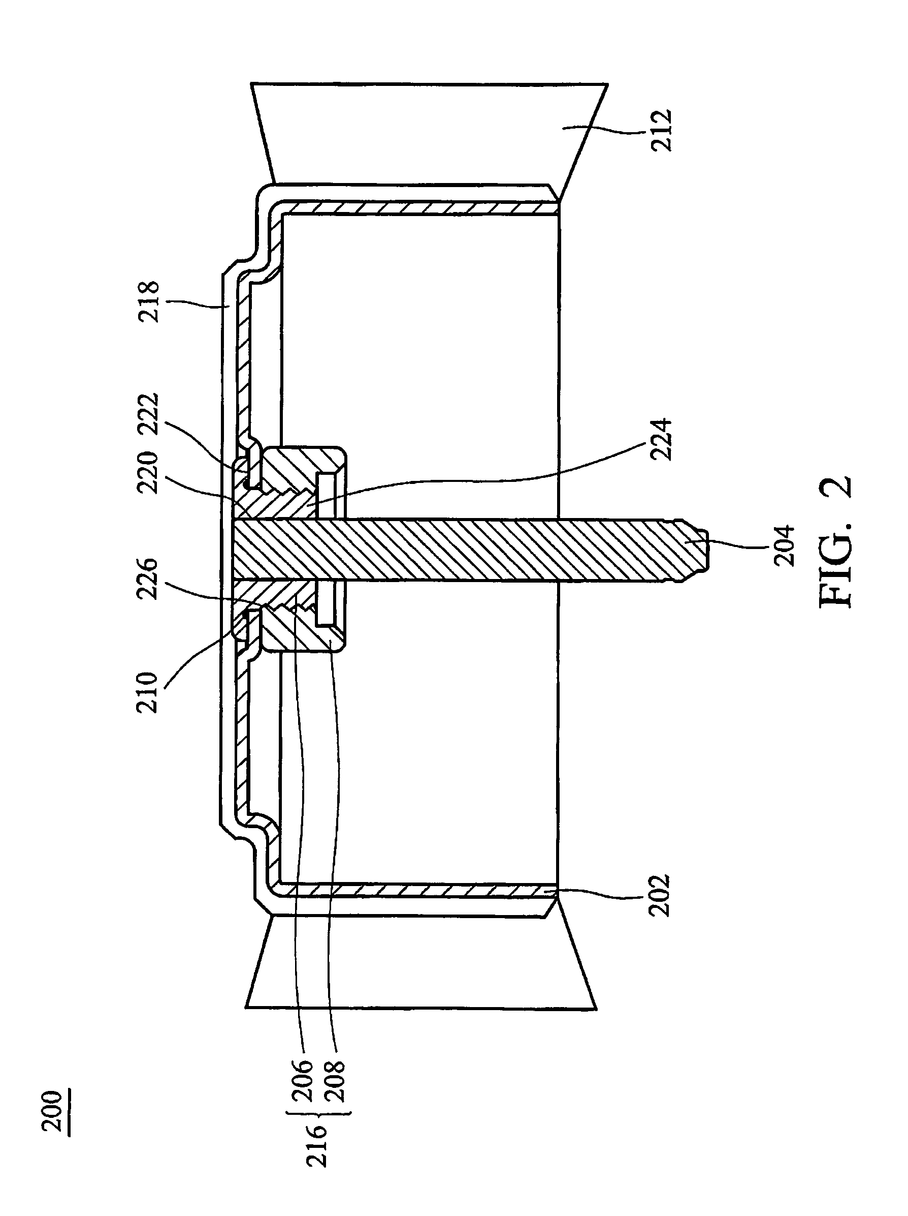
[0021]FIG. 2 shows an embodiment of a rotor structure 200. FIG. 3 is a partial exploded view of the rotor structure 200 in FIG. 2.

[0022]The rotor structure 200 comprises a case 202, a securing structure 216, and a rotating shaft 204 fixed to the case 202 by the securing structure 216.

[0023]The case 202 is the body of the rotor structure 200 and has a tubular shape. An opening 226 is disposed in an axle center on the bottom of the case 202 to enclose the securing structure 216. Specifically, a cross-section of the tubular shape can be circular, polygonal, or other similar shapes, and the opening 226 can be circular, polygonal, regular-patterned or irregular-patterned. The case 202 can be fabricated by punching or integral forming, and the material of the case 202 is metal, plastic or alloy.

[0024]When the rotor structure 200 is applied to a fan or other similar device, a fan blade 212 can be disposed surrounding periphery of the case 202. The fan blade 212 can be an axial-flow fan bla...


PUM

PropertyMeasurementUnit
radiusaaaaaaaaaa
elastic structureaaaaaaaaaa
sizeaaaaaaaaaa

Abstract

A fan and a rotor structure thereof. The rotor structure has a case, an upper linking structure, a lower structure, and a rotating shaft. The case has an opening at the axle center. The upper linking structure has a fixing portion and a threaded portion. The minimum radius of the fixing portion is longer than the radius of the opening. The threaded portion is disposed in the opening. The lower linking structure has a thread corresponding to the threaded portion. The upper linking structure and the lower linking structure is screwed together to secure the case therebetween. The rotating shaft is fixed in the upper linking structure or the lower linking structure.

Description

BACKGROUND OF THE INVENTION[0001]1. Field of the Invention[0002]The present invention relates to a fan and the rotor structure thereof.[0003]2. Description of the Prior Art[0004]Generally, in a conventional fan, the shaft and the case of the rotor structure are engaged by interference fit. In a large fan with significant size and weight, however, the shaft and the case may separate in operation due to the weight of the rotor structure. Typically, a rivet joint is used for large fans to engage the shaft and the case. With a rivet joint, the contact area of the shaft and the case increases to support the increased weight of the rotor structure.[0005]FIG. 1 illustrates a rotor structure 100 in a conventional large-scale fan. The rotor structure 100 has a case 102, a fan blade 104, a copper sheath 106, and a shaft 108. The shaft 108 is disposed in the copper sheath 106 by interference fit, and the copper sheath 106 is riveted to the case 102 by the rivet joint 110. Further, an electroco...

Claims


Application Information

Patent Timeline
Patent Type & Authority Patents(United States)
IPC IPC(8): F04D29/34F04D29/00F04D29/26H02K7/14
CPCF04D29/263F04D25/0613F04D29/023F05D2230/644F05D2300/611
Inventor CHEN, YING-CHICHUANG, TE-TSAITSAI, MING-SHI
Owner DELTA ELECTRONICS INC
Why Eureka
Try Eureka