Fixing apparatus and image forming apparatus

a technology of fixing apparatus and image forming apparatus, which is applied in the direction of electrographic process apparatus, instruments, induction heating, etc., can solve the problems of difficult to dramatically improve the startup time, long time, and high power consumption, so as to eliminate temperature unevenness, reduce temperature unevenness, and improve the effect of first-copy performan

Active Publication Date: 2008-10-14
SHARP KK
View PDF18 Cites 6 Cited by
  • Summary
  • Abstract
  • Description
  • Claims
  • Application Information

AI Technical Summary

Benefits of technology

[0043]With the fixing apparatus of this invention, because the heating roller is heated while rotating the heating roller during standby, even if heated locally by the partial heating means, it is possible to suppress temperature unevenness in the circumferential direction of the heating roller during standby, and it is possible to complete the return from standby mode to the temperature at which fixing is possible in a short period of time, so that good first-copy-out performance can be obtained. Further, it is possible to eliminate temperature unevenness due to temperature hysteresis in the circumferential direction of the heating roller even immediately after returning to the temperature at which fixing is possible, so that a good image without gloss unevenness or the like can be obtained.
[0044]With the image forming apparatus of the present invention, because a fixing apparatus having the above characteristics is provided, it is possible to complete the return from standby to the temperature at which fixing is possible in a short period of time, so that good first-copy-out performance can be obtained, and good image quality can be maintained.

Problems solved by technology

In a heating roller-type fixing apparatus, conventionally, an aluminum member with a large heat capacity, whose walls have been made somewhat thick, is used as the heating roller, but with this sort of heating roller, there are the problems that not only does the start time until reaching a predetermined temperature (for example, 180° C.) necessary for fixing become long, but power consumption also becomes high, and so a way of dealing with those problems is sought.
Of these configurations, with the configuration using a metal roller in (1), heat capacity is large in order to obtain rigidity as a roller structure, and so it is difficult to dramatically improve the startup time.
Also, with the film-sliding system in (2), the heat capacity of the heat generating layer is very small, so there is effect of shortening the startup time, but stable rotational driving is difficult, so this configuration is unsuitable for increasing speed.

Method used


Image

  • Fixing apparatus and image forming apparatus
  • Fixing apparatus and image forming apparatus
  • Fixing apparatus and image forming apparatus

Examples


Embodiment Construction

[0069]Hereinafter, the present invention will be described by way of illustrative embodiments with reference to the drawings.

[A] Image Forming Apparatus

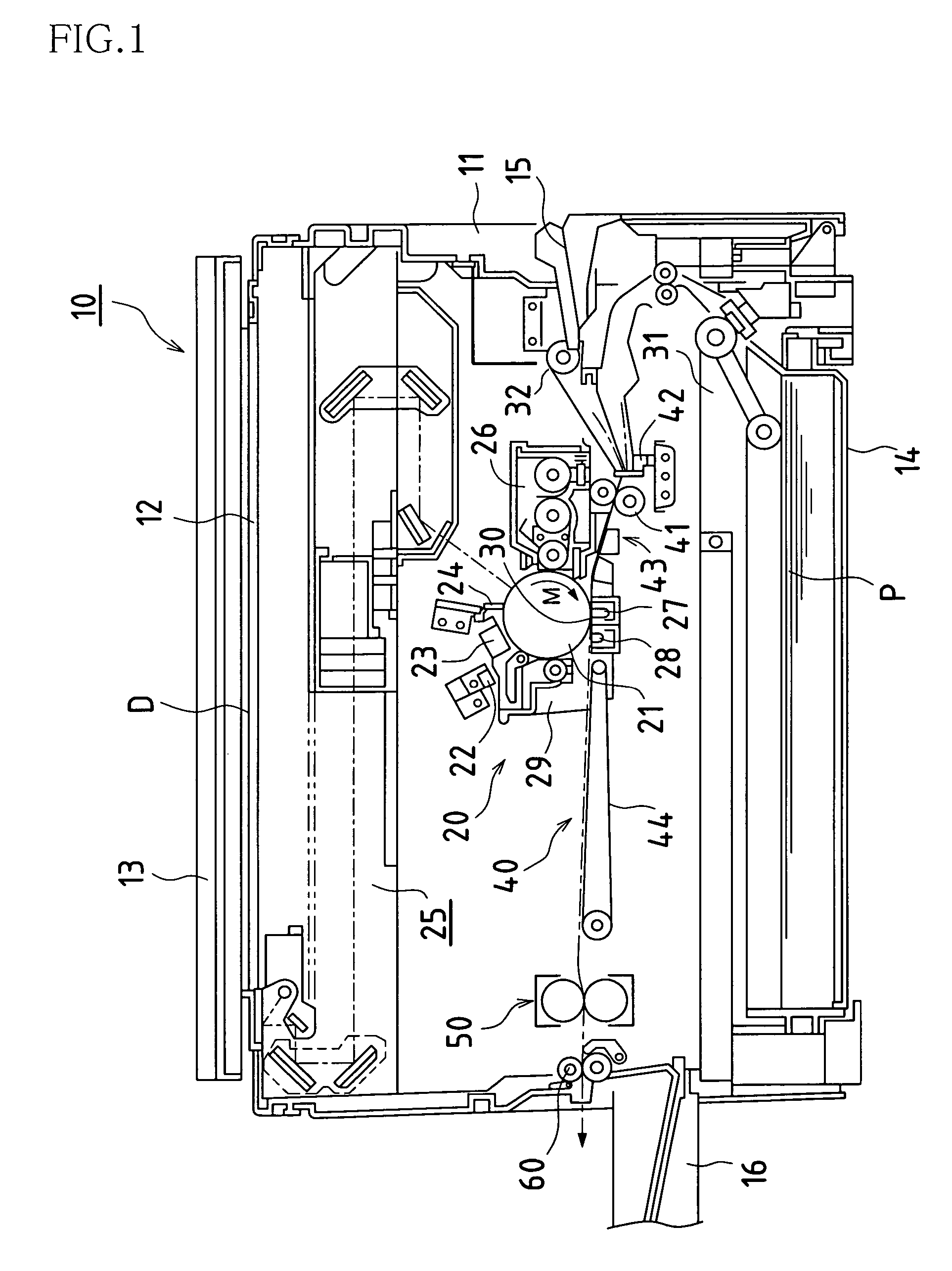
[0070]FIG. 1 is a cross-sectional view that shows an example of an image forming apparatus of the present invention.

[0071]An image forming apparatus 10 shown in FIG. 1 is provided with a casing-like apparatus main body 11, and inside that apparatus main body 11 an image forming portion 20 is disposed that forms an image with image forming processes such as charging, exposure, developing, transfer, and cleaning. Also, in the upper face of the apparatus main body 11, a glass platen 12 is disposed as an original placement stage, and a platen cover 13 is disposed that holds down an original D that has been set on this glass platen 12.

[0072]A control panel is disposed in the face front edge portion of the upper face of the apparatus main body 11 as an input / display means (not shown). In the bottom portion of the apparatus main body 11, a ...


PUM


Abstract

By controlling the temperature of a heating roller with high precision when in standby, good first-copy-out performance is obtained. In a fixing apparatus comprising a heating roller 1, a pressure roller 2, an induction coil 3a that generates magnetic flux, and a temperature detection member (such as a thermistor) 5 that detects the temperature of the heating roller 1, in which the heating roller 1 is caused to generated heat by generating an eddy current in a heat generating layer of the heating roller with magnetic flux generated by the induction coil 3a, the temperature of the heating roller 1 is controlled by disposing the temperature detection member 5 in a region where the maximum heat generating capacity of the heat generating portion of the heating roller 1 with induction heating is not less than 1 / e, and thus an unusual rise in the temperature of the heating roller 1 is suppressed.

Description

TECHNICAL FIELD[0001]The present invention relates to a fixing apparatus that fixes a toner image on recording material with heat and pressure, and an image forming apparatus using that fixing apparatus.BACKGROUND ART[0002]Recently, in electrophotographic image forming apparatuses, heating roller-type fixing apparatuses have come into practical use with which stable fixing is possible while having a small size. This sort of heating roller-type fixing apparatus is configured such the it is provided with a heating roller that transports, while heating, recording paper to which a toner image constituted from powdered developer (toner) has been transferred, and a pressure roller that transports the recording paper while pressing it against this heating roller, and by allowing the recording material (paper) to pass at a fixing point, which is a pressing portion (nip portion) between the heating roller and the pressure roller, the toner image on the recording material is melted and presse...

Claims


Application Information

Patent Timeline
Patent Type & Authority Patents(United States)
IPC IPC(8): G03G15/20H05B6/14
CPCG03G15/205
Inventor YAMAJI, HIROYUKI
Owner SHARP KK
Why Eureka
Try Eureka