
Polyester manufacturing apparatus and method

A technology for a manufacturing device and a manufacturing method, applied to a polyester manufacturing device and the field thereof, can solve the problems of reduced production efficiency, long distance, thermal stress damage, etc., and achieve the effects of improving production efficiency, high heating temperature, and reducing output

Inactive Publication Date: 2012-02-01
HITACHI LTD
View PDF2 Cites 0 Cited by
  • Summary
  • Abstract
  • Description
  • Claims
  • Application Information

AI Technical Summary

Problems solved by technology

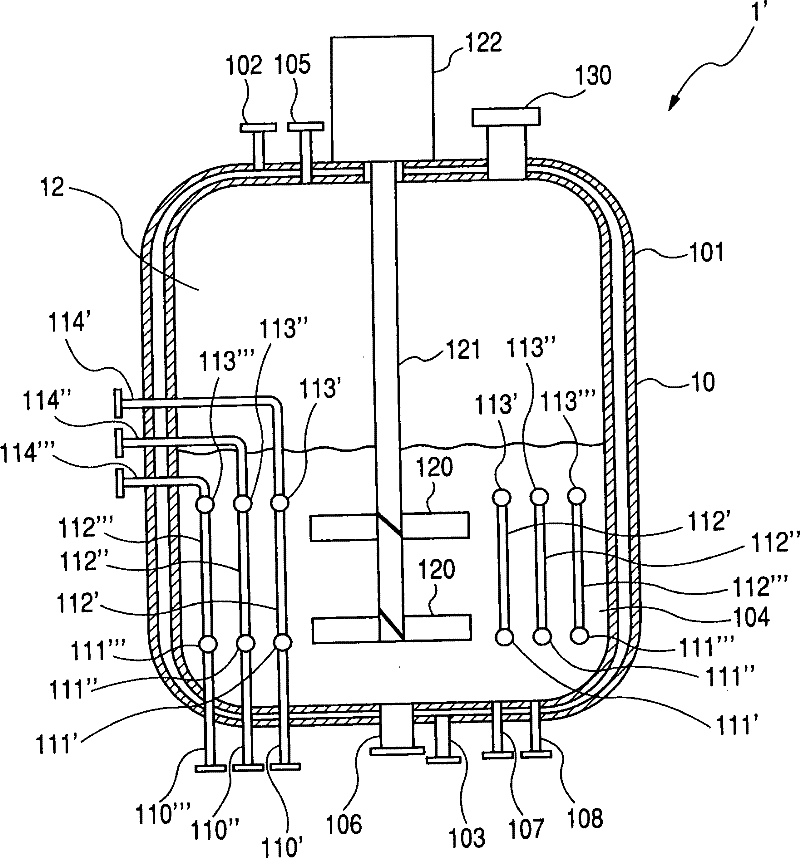
exist Figure 5a In the device described in Patent Document 2 shown, the upper and lower headers are respectively integrally formed in the circumferential direction, so there is a corresponding Figure 5b The distance is long, and the possibility of thermal stress damage becomes high
In addition, the possibility of such thermal stress damage becomes high under high-temperature conditions, so the reaction time becomes long and the amount of reaction by-products is large. Therefore, when the device of Patent Document 2 is used, it is inevitable that the The reaction is carried out at an unfavorable low temperature, resulting in a long reaction time and a large amount of reaction by-products, therefore, there is a problem of reduced production efficiency
[0008] In addition, in the first reactor described in the above-mentioned Patent Document 1, a plurality of heat transfer tubes are arranged in the upper and lower headers, and therefore, thermal stress due to thermal expansion in the circumferential direction of the headers may be caused during high-temperature operation. broken problem
The same problem also exists when dealing with the diethylene glycolization of ethylene glycol in the polymerization of polyethylene terephthalate and the acroleylation of 1,3-propanediol in the polymerization of polytrimethylene terephthalate. occur

Method used


Image

  • Polyester manufacturing apparatus and method
  • Polyester manufacturing apparatus and method
  • Polyester manufacturing apparatus and method

Examples

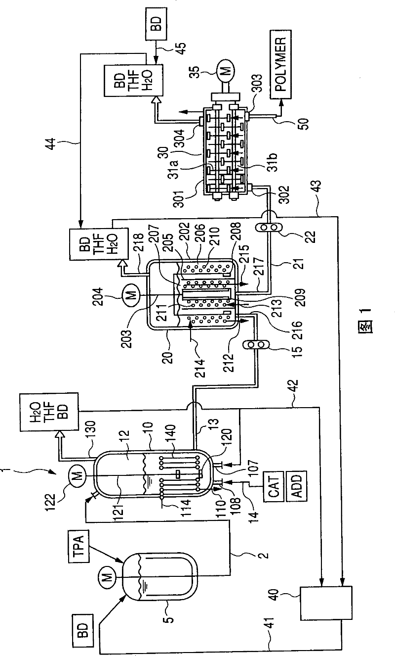

Embodiment Construction

[0029] Embodiments of the production apparatus and method of the polyester-based polymer of the present invention will be described in more detail.

[0030] The present invention relates to a continuous production device for polyester-based polymers, wherein the first reactor has the following characteristics: the liquid to be treated containing dicarboxylic acids and glycols is stirred and heated by the heat of the gas phase or liquid phase heat medium. By heating, the liquid to be treated undergoes an esterification reaction to produce an oligomer. In the continuous production apparatus of polyester-based polymers of the present invention, in addition to the first reactor, a second reactor for polycondensing oligomers from the first reactor to produce polymers with a low degree of polymerization may be further provided. A second reactor; a third reactor for further polycondensing the low-polymerization polymer from the second reactor to produce a polymer with a high degree o...


PUM

PropertyMeasurementUnit
degree of polymerizationaaaaaaaaaa

Abstract

The present invention provides a manufacturing apparatus of polyester and a method for manufacturing polybutylene terephthalate, wherein a first processor of preparing an oligomer is improved in efficiency. The apparatus for manufacturing polybutylene terephthalate in the present invention comprises, at least, a first processor 1 including a vertical cylindrical esterification processor 10, a lower header tube constituted by a plurality of unit lower header tubes 111a-d, an upper header tube constituted by a plurality of unit upper header tubes 113a-d, heat transfer tubes 112a-d that are made of a plurality of communicating tubes connecting the unit lower header tubes 111a-d and the unit upper header tubes 113a-d, which are vertically facing each other, so as to enable a vapor phase or liquid phase heat medium to be communicable therethrough, and an agitation blade 120, characterized in that the respective unit lower header tubes 111a-d and the respective unit upper header tubes 113a-d are formed with a heat medium outflow and inflow unit.

Description

technical field [0001] The present invention relates to polybutylene terephthalate, polyethylene terephthalate, polytrimethylene terephthalate, polybutylene succinate, polyethylene succinate, etc. A continuous production method and apparatus for ester-based polymers. Background technique [0002] These polyesters are synthesized by using dicarboxylic acids and diols as raw materials, adding a catalyst to these mixtures, and then passing through an esterification step and a polymerization step. In the esterification process, the carboxyl groups of the two dicarboxylic acids undergo esterification reactions with diols to form monomers, and the monomers undergo polycondensation reactions to form oligomers with an average degree of polymerization of about 1-10. As one of the polyester-based polymers, a method for producing polybutylene terephthalate (hereinafter referred to as PBT) and an apparatus thereof are known in JP-A-62-195017 (Patent Document 1), JP-A The device disclo...

Claims


Application Information

Patent Timeline
Patent Type & Authority Patents(China)
IPC IPC(8): C08G63/78C08G63/16
CPCB01F7/00341B01J19/20B01F15/066B01J2219/185B01J2219/00081C08G63/785B01J19/18F28D7/1669B01F7/00633B01J2219/00083B01J19/1862B01J2219/182B01F27/113B01F27/191B01F35/93
Inventor 冈宪一郎松尾俊明上川将行佐世康成
Owner HITACHI LTD
Learn More