Tire monitor radio circuit and tire monitor system

a technology of radio circuit and tire monitor, which is applied in vehicle tyre testing, digital computer details, instruments, etc., can solve the problems of inability to transmit accurate information and excessive radio transmission level of first communication device, and achieve the effect of improving communication reliability

Inactive Publication Date: 2008-09-09
PACIFIC INDUSTRIAL CO LTD
View PDF10 Cites 9 Cited by
  • Summary
  • Abstract
  • Description
  • Claims
  • Application Information

AI Technical Summary

Benefits of technology

[0008]Therefore, an object of the present invention is to provide a tire monitor radio circuit which can improve communication reliability and a tire monitor system provided with the tire monitor radio circuit.

Problems solved by technology

Furthermore, there is a time when a reception level of radio transmission from a first communication device is excessively high at a second communication device.
The ASK modulation and demodulation result in the following problem.
Moreover, since reduction in the transmission output renders the signal weaker against noise, accurate information still cannot be transmitted.

Method used


Image

  • Tire monitor radio circuit and tire monitor system
  • Tire monitor radio circuit and tire monitor system
  • Tire monitor radio circuit and tire monitor system

Examples


first embodiment

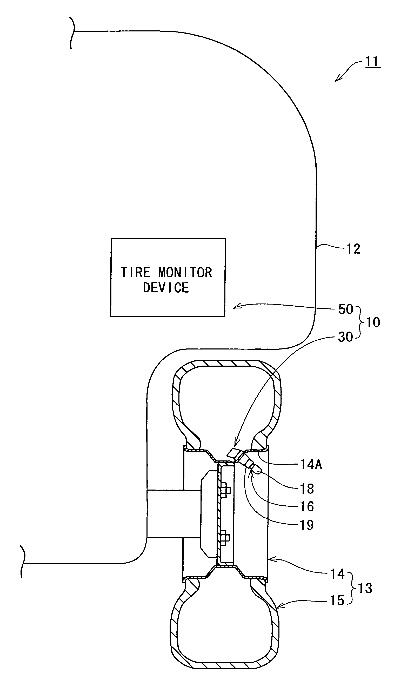
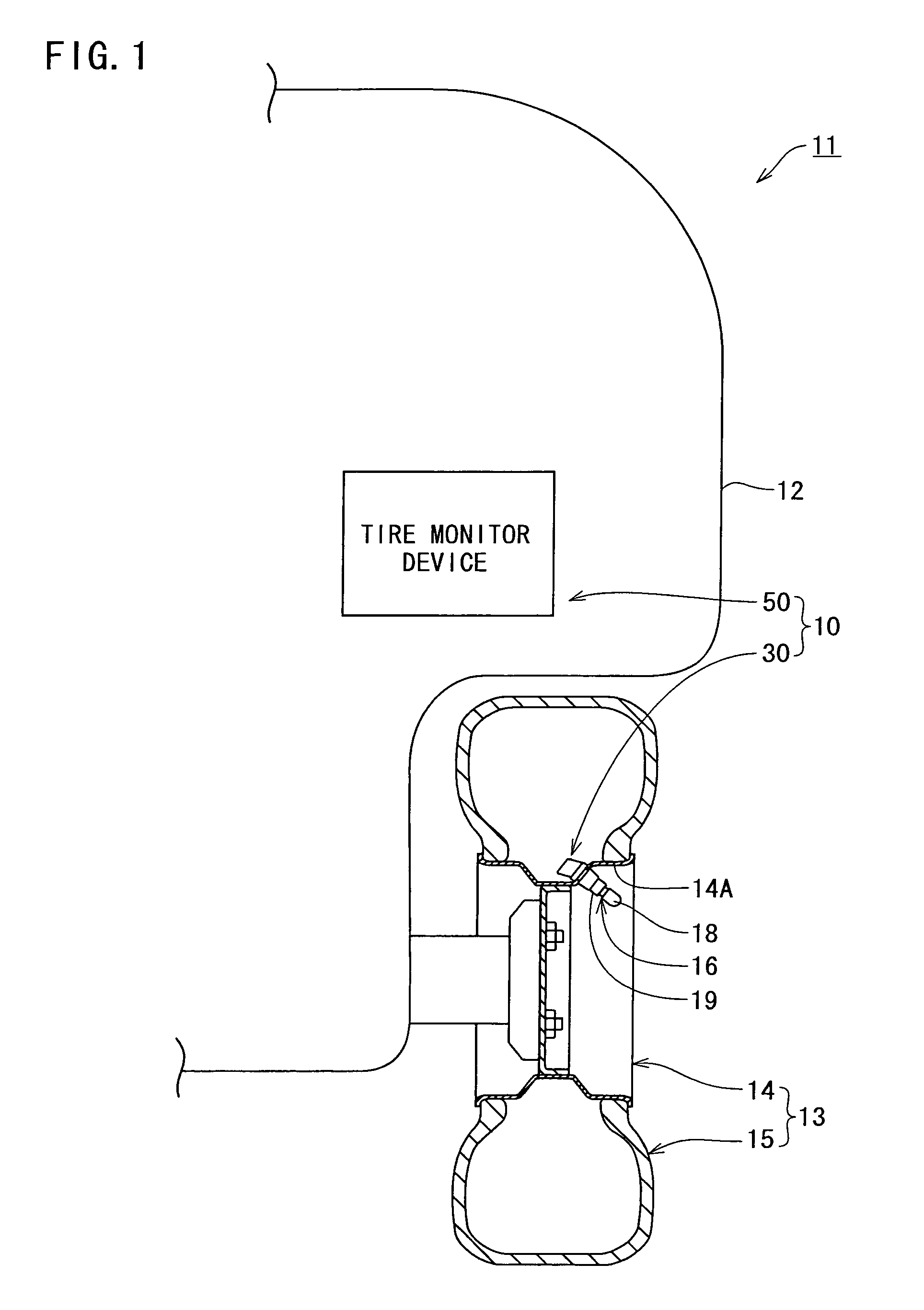
[0026]A first embodiment of the present invention will be described with reference to FIGS. 1 to 5. FIG. 1 illustrates a tire monitor system 10 in accordance with the invention. The tire monitor system 10 comprises, for example, four tire pressure detectors 30 provided on respective wheels 13 of a vehicle 11 such as automobile and a single tire monitor device 50 provided on a body 12 of the vehicle 11. Only one of the wheels 13 is shown in FIG. 1.

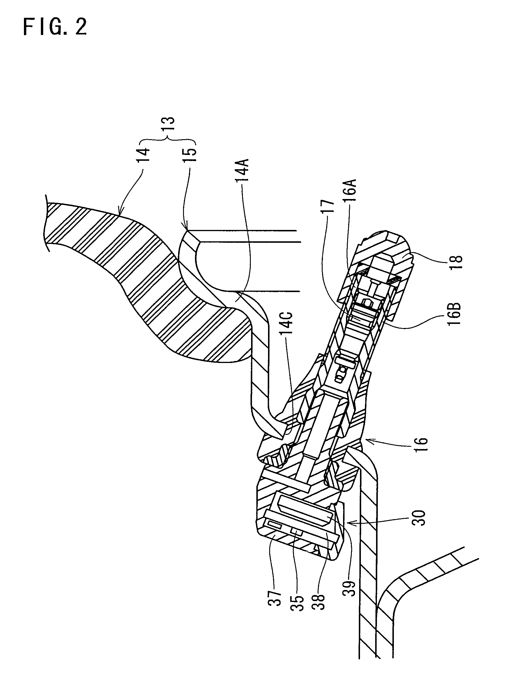
[0027]Each wheel 13 is comprised of a tire wheel 14 having a rim 14A and a tubeless tire 15 fitted with the rim 14A. The rim 14 is formed with a valve mount hole 14C as shown in FIG. 2. A tire valve 16 is inserted through and fixed to the valve mount hole 14C. The tire valve 16 comprises a cylindrical valve stem 16A with two open ends and a valve core 17 with a check-valve structure disposed in the valve stem 16A. The tire valve 16 has a distal end protruding to an inner circumferential surface side of the rim 14A. On the other hand, the ti...

second embodiment

[0041] when the modulation circuit 54 has been switched from the oscillatory state to the non-oscillatory state, the resistance 71A is conductively connected between both terminals of the coil 59 of the antenna resonance circuit 60. Accordingly, resonance current due to damped oscillation flows into the resistance 71A, whereby electric energy is consumed. Consequently, statically determinate time of damped oscillation can be reduced.

[0042]FIG. 7 illustrates a third embodiment of the invention. The third embodiment differs from the first embodiment mainly in the arrangement of a resistance damping circuit 72. More specifically, the resistance damping circuit 72 is connected in series with the switching element 72B and the resistance 72A between both terminals of the capacitor 58 of the antenna resonance circuit 60. Other arrangements of the third embodiment are same as those of the second embodiment. The third embodiment can achieve the same effect as the second embodiment.

[0043]FIG....


PUM


Abstract

A tire monitor radio circuit includes a control circuit delivering a binary digital baseband signal, a modulation circuit having an oscillation circuit generating a carrier wave and switched between an oscillatory and a non-oscillatory states, an antenna resonance circuit having a coil and a capacitor both connected together, a resistance damping circuit having a switching element and a resistance and connected to the antenna resonance circuit, the resistance damping circuit being switchable between an operative and an inoperative states, and a compensation circuit putting the resistance damping circuit into the operative state when the modulation circuit is switched to the non-oscillatory state, the compensation circuit returning the resistance damping circuit to the non-operative state when or before the modulation circuit has been or is switched to the oscillatory state. When he resistance damping circuit is on the operative state, resonance current of the damped oscillation in the antenna resonance circuit is applied to the resistance, and the resistance serves as a damper thereby to reduce statically determinate time of damped oscillation. As a result, the digital signal can accurately be detected from the carrier wave at the reception side. Consequently, reliability in the communication can be improved.

Description

BACKGROUND OF THE INVENTION[0001]1. Field of the Invention[0002]The present invention relates to a tire monitor radio circuit for performing radio transmission to a tire pressure detector mounted on a wheel of a vehicle and a tire monitor system provided with the radio circuit.[0003]2. Description of the Related Art[0004]Tire monitor systems of the above-described type generally comprise a tire monitor device mounted on a body of a vehicle and tire pressure detectors mounted on respective tires of the vehicle. Information about inner pressure of each tire is transmitted by radio between the vehicle body and each wheel. JP-A-2005-119370 discloses one of such tire monitor systems. In one of known communication manners, a tire monitor device provided at the vehicle body side delivers a trigger signal by radio. In reply to the trigger signal, a tire pressure detector transmits results of detection of tire pressure by radio. In this case, the tire monitor device carries out an amplitude ...

Claims


Application Information

Patent Timeline
Patent Type & Authority Patents(United States)
IPC IPC(8): G01M17/02
CPCB60C23/0433B60C23/0442
Inventor KATOU, MICHIYA
Owner PACIFIC INDUSTRIAL CO LTD
Why Eureka
Try Eureka