Method for transmitting packet in wireless access network based on wavelength identification code scheme

Inactive Publication Date: 2008-09-02
ELECTRONICS & TELECOMM RES INST
View PDF7 Cites 23 Cited by
  • Summary
  • Abstract
  • Description
  • Claims
  • Application Information

AI Technical Summary

Benefits of technology

[0010]Therefore, the present invention has been made in view of the above problems, and it is an object of the present invention to provide a method for transmitting a packet in a wireless access network based on a wavelength identification code scheme, the method capable of improving wavelength utilization and simplifying the packet transmission process by assigning a unique wavelength to each of RNCs (Radio Network Controllers) for transmitting and receiving data data packets through the assigned wavelengths, thereby supporting high-speed mobility services.

Problems solved by technology

Further, a packet transmission process is complicated in the conventional access network and the capacity of the conventional access network cannot accommodate a fourth generation mobile communication system, which guarantees a bandwidth of more than several Mbits / s per mobile subscriber.
The capacity of the backbone network is sufficient for a current wired network, but high-speed data services of large capacity cannot be provided to a mobile terminal subscriber because the capacity of the conventional access network is limited.
However, the GPRS is complicated because it is made up of two stages.
Further, a procedure of transmitting the packet in the GPRS is not efficient because a control signal and a data protocol stack are separated from each other (a reference document: 3GPP TS 23.060, “GPRS Service Description Stage 2”, October, 2001).
However, there is a disadvantage in that the conventional systems and methods cannot fully solve the problem with packet transmission capability of a wireless access network in terms of core requirements of bandwidth and QoS (quality of service) for Internet services.
Further, there is another disadvantage in that the conventional systems and methods have been posed a complexity in implementing high-speed mobility services.

Method used


Image

  • Method for transmitting packet in wireless access network based on wavelength identification code scheme
  • Method for transmitting packet in wireless access network based on wavelength identification code scheme
  • Method for transmitting packet in wireless access network based on wavelength identification code scheme

Examples


Embodiment Construction

[0021]Now, preferred embodiments of the present invention will be described in detail with reference to the annexed drawings. In the following description, a variety of specific elements such as constituent elements are shown. The description of such elements has been provided only for a better understanding of the present invention.

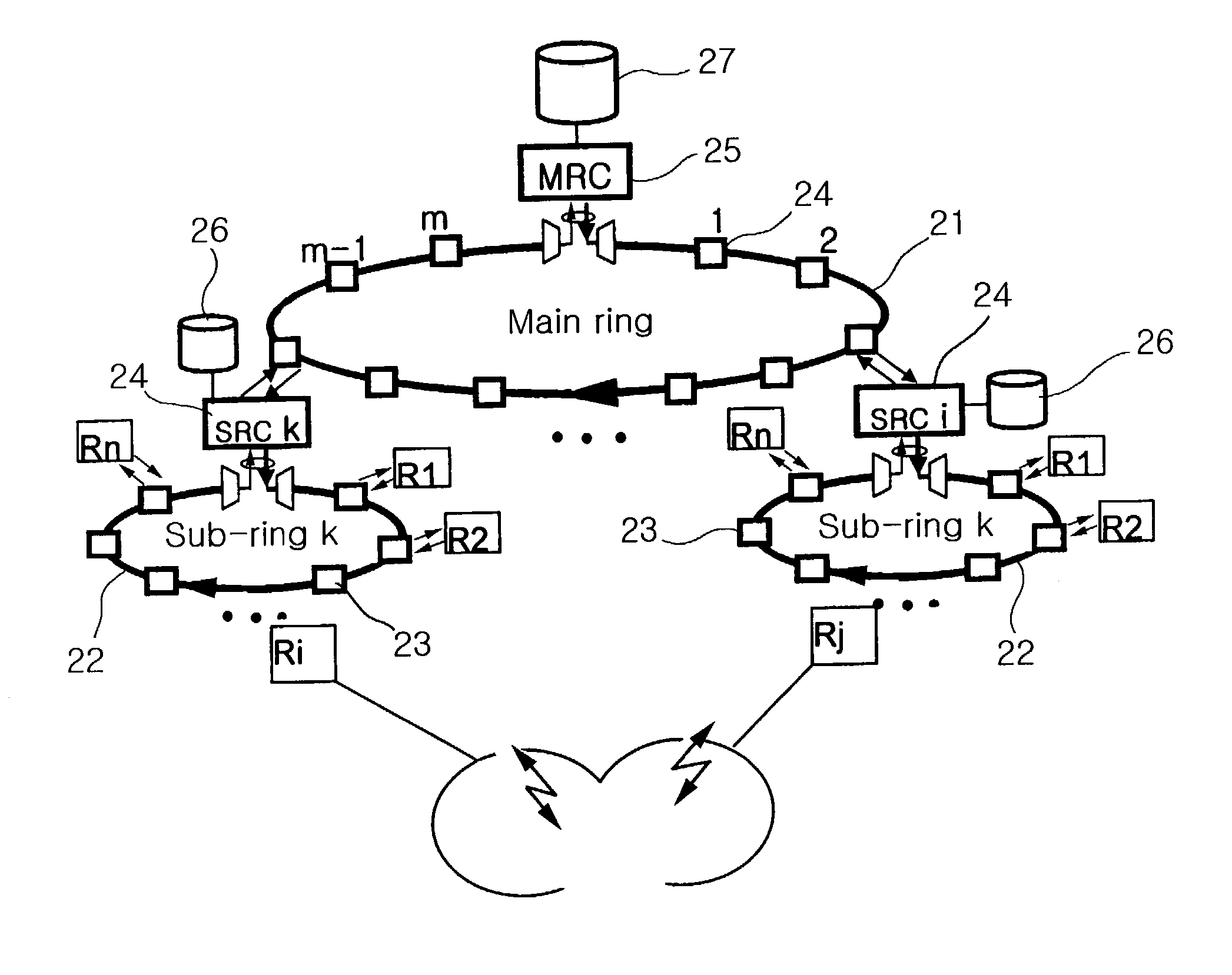
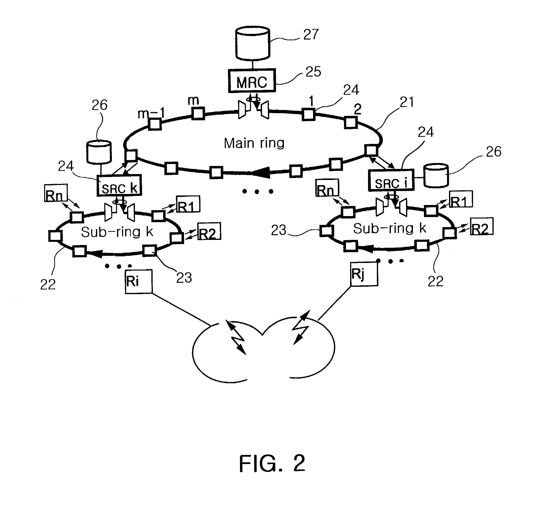
[0022]FIG. 2 is a view showing a DWDM (Dense Wavelength Division Multiplexing) wireless access network architecture based on a wavelength identification code scheme as employed in the present invention. As shown in FIG. 2, the wireless access network based on the DWDM scheme comprises an MR (main-ring) 21 and SRs (sub-rings) 22. One sub-ring 22 is connected to n number of RNCs 23 where the “n” is a positive integer and a unique wavelength is assigned to each RNC 23. An area of the sub-rings 22 is similar to that of a line-switched mobile communication switching system, and the packet transmission between the RNCs 23 within the same sub-ring 22 is perform...


PUM


Abstract

A method for transmitting a packet in a wireless access network based on a wavelength identification code scheme. The method comprises the steps of connecting n number of RNCs (Radio Network Controllers) to one sub-ring where the “n” is a positive integer, and assigning a unique wavelength to each RNC; identifying a packet to be transmitted between the RNCs located within a same sub-ring using the assigned unique wavelength, and transmitting the packet through an SRC (Sub-Ring Controller); connecting m number of SRCs to one main-ring where the “m” is a positive integer, and assigning a unique wavelength to each SRC; and detaching a wavelength identification code from the packet to be transmitted between the RNCs located within different sub-rings, and transmitting the packet having the encapsulated wavelength identification code through an MRC (Main-Ring Controller).

Description

BACKGROUND OF THE INVENTION[0001]1. Field of the Invention[0002]The present invention relates to a method for transmitting a packet in a packet-mode wireless access network, and more particularly to a method for transmitting a packet in a packet-mode wireless access network, which can guarantee a bandwidth by assigning a unique wavelength to each RNC (Radio Network Controller) in a packet-mode wireless access network, improve access network utilization and simplify packet transmission by transmitting / receiving the packet being identified by the unique wavelength, and provide high-speed paging and broadcasting services by commonly assigning a specific shared wavelength to all RNCs.[0003]2. Description of the Related Art[0004]Recently, as numbers of wireless Internet users and a demand of multimedia services increase, a need for large-capacity packet transmission services has increased. Further, a B-ISDN (Broadband Integrated Services Digital Network) is being rapidly developed to acc...

Claims


Application Information

Patent Timeline
IPC IPC(8): H04B10/20H04L12/46H04L12/56H04Q11/00H04W36/12H04W40/00H04W40/02H04W40/24H04W40/36H04W72/04H04W74/00H04W92/22
CPCH04L12/4633H04L12/4637H04L45/62H04Q11/0067H04W92/22H04Q11/0066H04Q2011/0077H04W40/00H04W40/02H04W40/248H04W40/36H04W72/0406H04W74/00H04W36/12Y02D30/70H04W72/20H04L12/46H04L12/42H04J14/02
Inventor KIM, BYOUNG WHIYU, JEA HOONKANG, MIN HO
Owner ELECTRONICS & TELECOMM RES INST
Why Eureka
Try Eureka