
Punch and drill machine for a structural angle

a technology for structural angles and punching machines, applied in the direction of portable punching machines, manufacturing tools, transportation and packaging, etc., can solve the problems of difficult, if not impossible, positioning of punching holes

Inactive Publication Date: 2008-09-02
CARL DAN PEDDINGHAUS
View PDF12 Cites 14 Cited by
  • Summary
  • Abstract
  • Description
  • Claims
  • Application Information

AI Technical Summary

Benefits of technology

"The present invention provides a system for making holes in the legs of a structural angle that can accommodate various design features and improve efficiency. The system includes a machine with a first frame, a movable second frame, and a movable carriage. A punch and drill are mounted on the carriage for creating holes in the angle. The system allows for efficient and accurate positioning of the punch and drill, resulting in non-circular hole configurations and reduced manufacturing costs. The drill can also be used to make smaller holes than the thickness of the material. Overall, the system provides a versatile and efficient tool for making holes in structural angles."

Problems solved by technology

Further, because the drill can be used to drill holes in either leg of the angle (by removing and repositioning the angle, if necessary), holes can be drilled in either leg of the angle at locations that would be difficult, if not impossible, to punch.

Method used


Image

  • Punch and drill machine for a structural angle
  • Punch and drill machine for a structural angle
  • Punch and drill machine for a structural angle

Examples


Embodiment Construction

[0073]While this invention is susceptible of embodiment in many different forms, this specification and the accompanying drawings disclose only one specific form as an example of the use of the invention. The invention is not intended to be limited to the embodiment so described, and the scope of the invention will be pointed out in the appended claims.

[0074]For ease of description, the apparatus operating in accordance with this invention is described in the normal (upright) operating position, and terms such as upper, lower, horizontal, etc., are used with reference to this position.

[0075]The apparatus of this invention can have certain conventional components and control mechanisms the details of which, although not fully illustrated or described, will be apparent to those having skill in the art and an understanding of the necessary functions of such components and mechanisms.

[0076]Some of the Figures illustrating the preferred embodiment of the apparatus of the present inventio...


PUM

PropertyMeasurementUnit
lengthaaaaaaaaaa
lengthaaaaaaaaaa
structural angleaaaaaaaaaa

Abstract

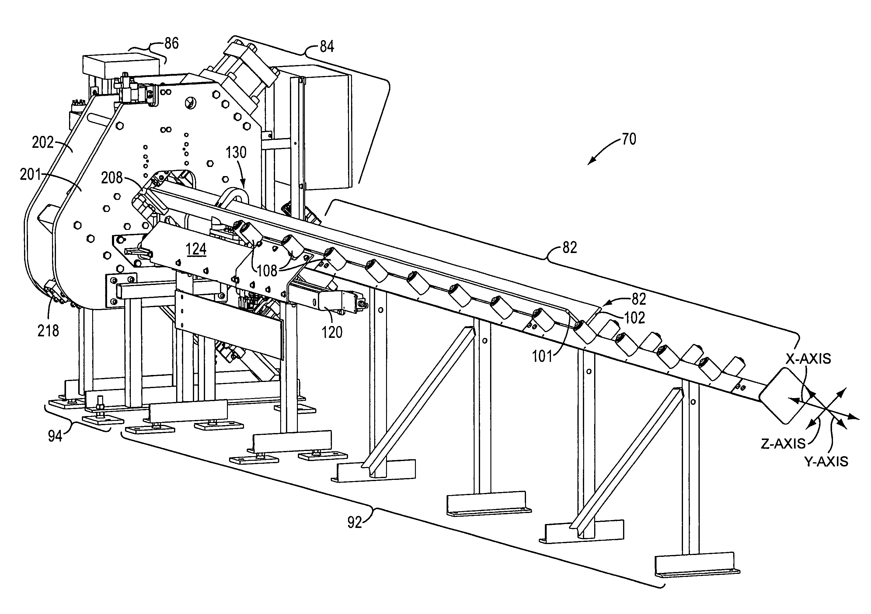
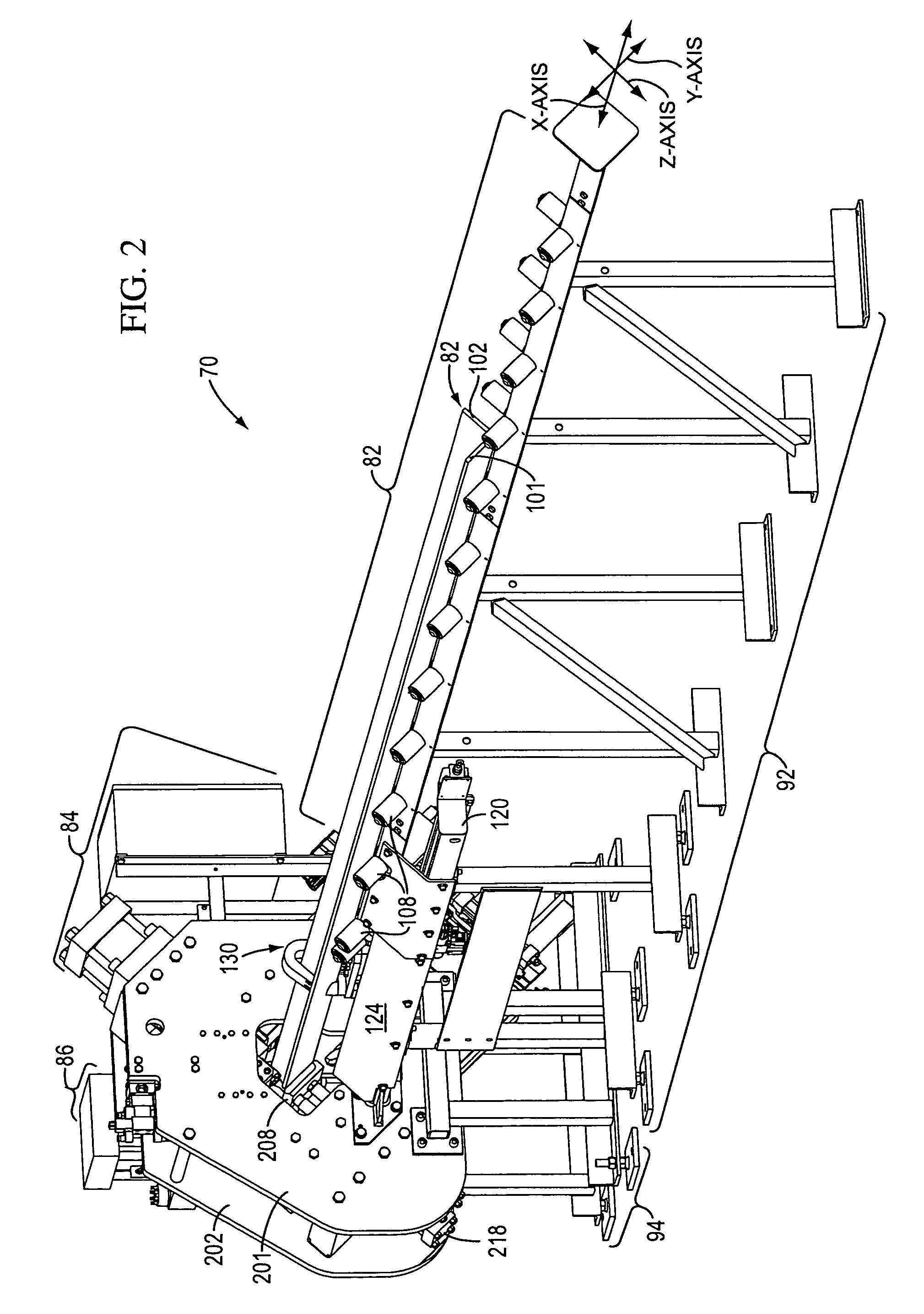
A machine is provided for making holes in the legs of a structural angle oriented lengthwise along the X-axis of a mutually orthogonal X, Y, and Z-axis coordinate system. The machine includes a first or main frame, a second frame moveable along the Y-axis relative to the first frame, and a carriage moveable along the Z-axis relative to the second frame. A punch is mounted on the second frame for punching a first hole in the first leg of the angle. A drill is mounted on the carriage for drilling a second hole in the second leg of the angle. The punch has a punch operating axis along which the punch moves longitudinally to punch the first hole and which is parallel to the Z-axis. The drill has a drill feed operation axis along which the drill moves longitudinally to drill the second hole and which is parallel to the Y-axis. The drill and the punch are oriented with the drill feed operation axis and the punch operation axis together defining a common plane.

Description

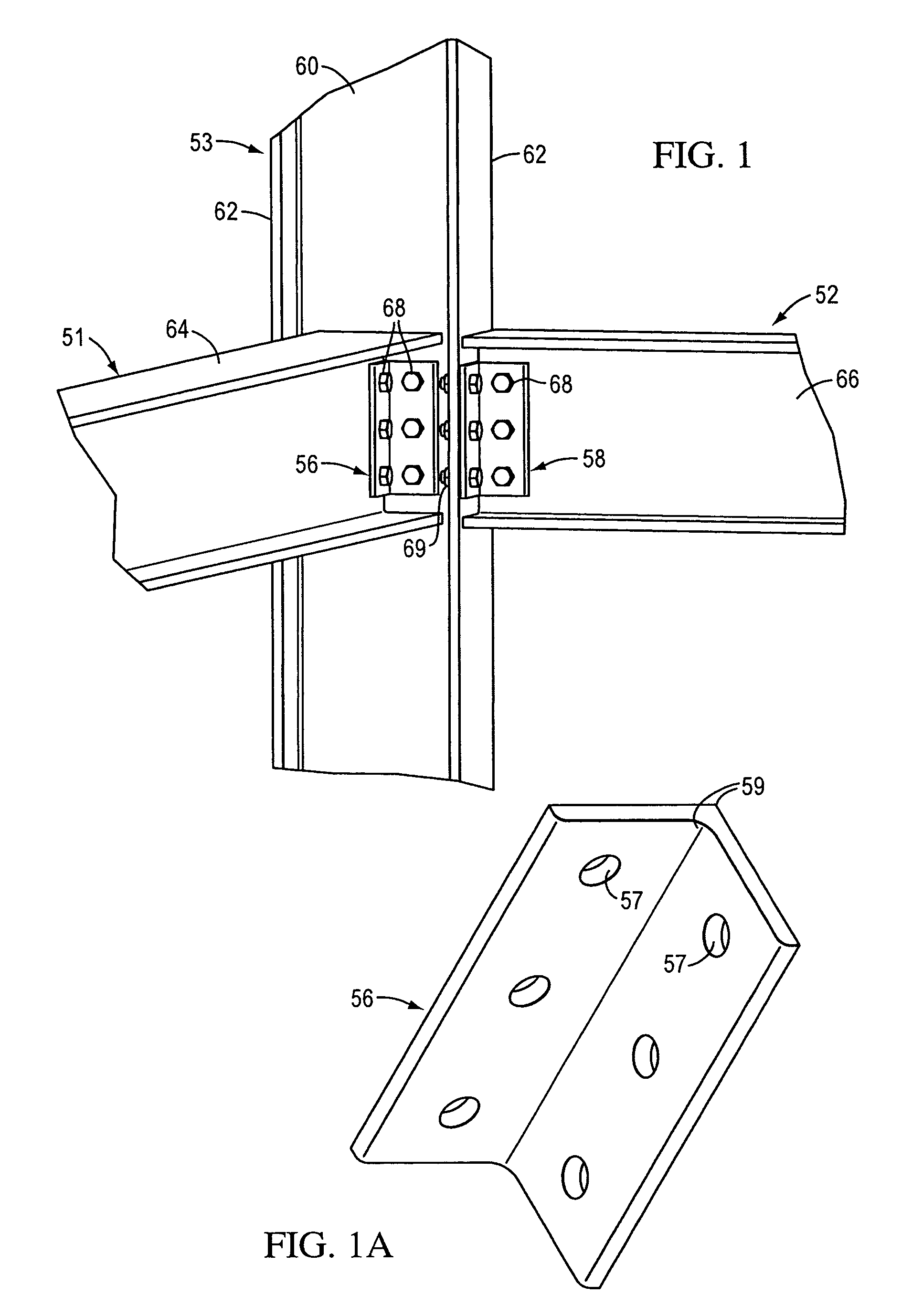
TECHNICAL FIELD[0001]This invention relates to a system for punching and drilling holes in a structural angle.BACKGROUND OF THE INVENTION AND TECHNICAL PROBLEMS POSED BY THE PRIOR ART[0002]Preparation of a structural angle for further use may require drilling, punching, and severing portions of the angle to create a configuration needed for the particular end use application (e.g., installation in a structural steel frame of a building or bridge, installation in a vehicle, installation on or in a machine or other assembly, etc.). Conventional machines exist for performing some or a number of these processing operations.[0003]Structural angles may have to be provided in appropriate lengths for being erected in specific structures or used in other applications. Methods for creating one or more shorter segments from a length of angle stock include severing the shorter segments from a longer length of angle stock with a shearing apparatus. See, for example, the shearing apparatus descri...

Claims


Application Information

Patent Timeline
Patent Type & Authority Patents(United States)
IPC IPC(8): B21D53/00B23P11/00B23Q37/00
CPCB21D28/243B23B41/003B23P23/02Y10T408/6757Y10T29/49829Y10T408/54Y10T29/5107Y10T408/356Y10T29/5116Y10T83/9382
Inventor SIMEK, ERIC CHRISTOPHER
Owner CARL DAN PEDDINGHAUS
Learn More