
Delay line circuit

a delay line and circuit technology, applied in the field of synchronous circuits, can solve the problems of increasing the time delay introduced by the internal circuitry, the internal clock signal to be phase shifted relative to the external clock signal, and the command applied to the memory device may no longer be valid, so as to achieve the effect of increasing the drive-to-load ratio

Active Publication Date: 2008-08-26
MICRON TECH INC
View PDF10 Cites 19 Cited by
  • Summary
  • Abstract
  • Description
  • Claims
  • Application Information

AI Technical Summary

Benefits of technology

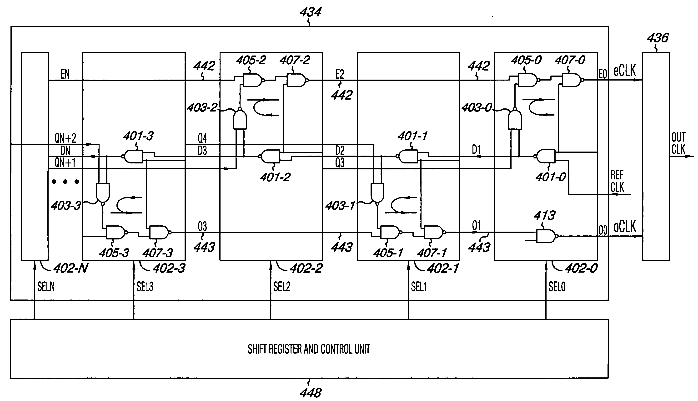
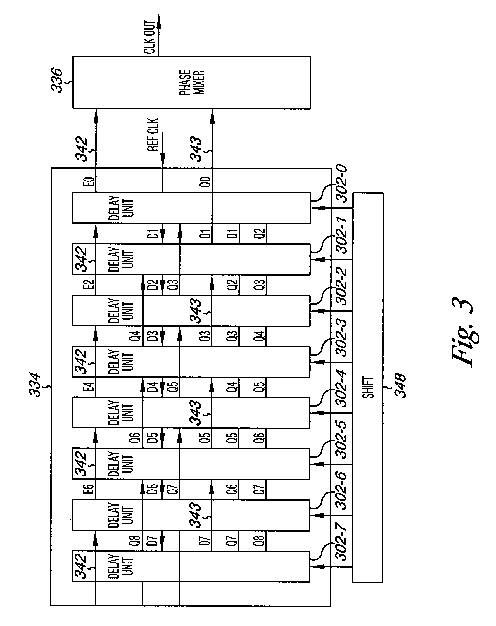
The present invention provides methods, circuits, devices, and systems including synchronous circuits. One embodiment includes a coarse delay line with a number of delay units coupled together and to an even clock line and an odd clock line. The delay units are coupled to the clock lines in a configuration intended to restrict an increase in delay as additional delay units are added. The method includes providing a reference clock to a first delay unit and coupling even and odd delay units to the clock lines to generate intermediate clocks. A phase mixer is used to combine the clocks. The technical effect is to provide a synchronized clock signal with reduced delay and increased accuracy.

Problems solved by technology

Internal circuitry in the memory device that generates the internal clock signal introduces some time delay, causing the internal clock signal to be phase shifted relative to the external clock signal.
As the frequency of the external clock signal increases, however, the time delay introduced by the internal circuitry becomes more significant.
This is true because as the frequency of the external clock signal increases, the period of the signal decreases and thus even small delays introduced by the internal circuitry correspond to significant phase shifts between the internal and external clock signals.
As a result, the commands applied to the memory device may no longer be valid by the time the internal clock signal clocks the latches.
These clock perturbations may not be desirable, especially when an electronic device, e.g., a memory device is operated at significantly high clock frequencies, e.g., 800 MHz or higher.
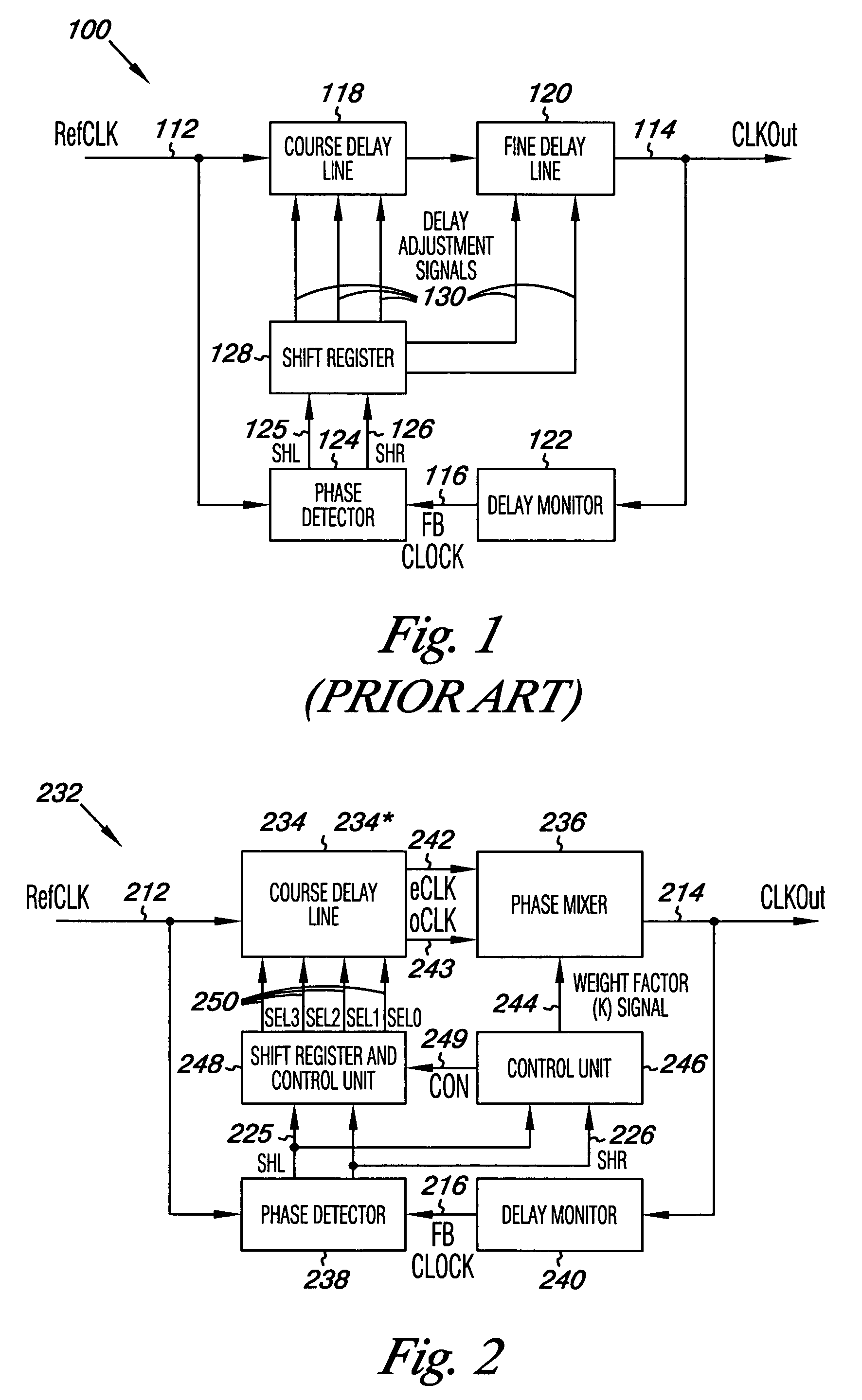
Furthermore, as reference clock frequencies increase, the DLL architecture in FIG. 1 may not be suitable to adequately control coarse shifting at such high frequencies, which may negatively affect the signal integrity of the ClkOut 114 and may also delay the establishment of a lock condition.

Method used


Image

  • Delay line circuit
  • Delay line circuit
  • Delay line circuit

Examples


Embodiment Construction

[0022]Methods, circuits, devices, and systems are provided, including a delay line for a synchronization circuit, e.g., a delay-locked loop. One method includes providing a reference clock to a first delay unit in a delay line. The delay line includes a number of delay units coupled together. Even delay units, among the delay units, are coupled to an even clock line to generate a first intermediate clock. Odd delay units are coupled to an odd clock line to generate a second intermediate clock. The even and odd delay units are coupled to the even and odd clock lines in a configuration intended to restrict an increase to intrinsic delay as additional delay units are coupled to the number of delay units.

[0023]In various embodiments, a delay line is provided which has an improved delay path over previous delay line paths. That is, the delay path may produce less intrinsic delay, less duty cycle distortion, and consume less power than previous delay path configurations.

[0024]FIG. 2 illus...


PUM


Abstract

Methods, circuits, devices, and systems are provided, including a delay line for a delay-locked loop. One method includes providing a reference clock to a first delay unit in a delay line. The delay line includes a number of delay units coupled together. Even delay units, among the delay units, are coupled to an even clock line to generate a first intermediate clock. Odd delay units are coupled to an odd clock line to generate a second intermediate clock. The even and odd delay units are configured to in a manner intended to restrict an increase in drive to load ratio and to intrinsic delay as additional delay units are coupled to the number of delay units.

Description

TECHNICAL FIELD[0001]The invention relates generally to integrated circuit memory devices, and more particularly, to synchronous circuits for the same.BACKGROUND OF THE INVENTION[0002]In synchronous integrated circuits, the integrated circuit is clocked by an external clock signal and performs operations at predetermined times relative to the rising and falling edges of the applied clock signal. Examples of synchronous integrated circuits include synchronous memory devices such as synchronous dynamic random access memories (SDRAMs), synchronous static random access memories (SSRAMs), and packetized memories like SLDRAMs and RDRAMs, and include other types of integrated circuits as well, such as microprocessors. The timing of signals external to a synchronous memory device is determined by the external clock signal, and operations within the memory device typically are synchronized to external operations. For example, commands are placed on a command bus of the memory device in synch...

Claims


Application Information

Patent Timeline
Patent Type & Authority Patents(United States)
IPC IPC(8): H03L7/06
CPCG11C7/222G11C7/22
Inventor KIM, KANG YONGKWAK, JONGTAE
Owner MICRON TECH INC
Learn More