
Data communication system, data transmitter and data receiver

Inactive Publication Date: 2008-08-19
SONY CORP
View PDF17 Cites 238 Cited by
  • Summary
  • Abstract
  • Description
  • Claims
  • Application Information

AI Technical Summary

Benefits of technology

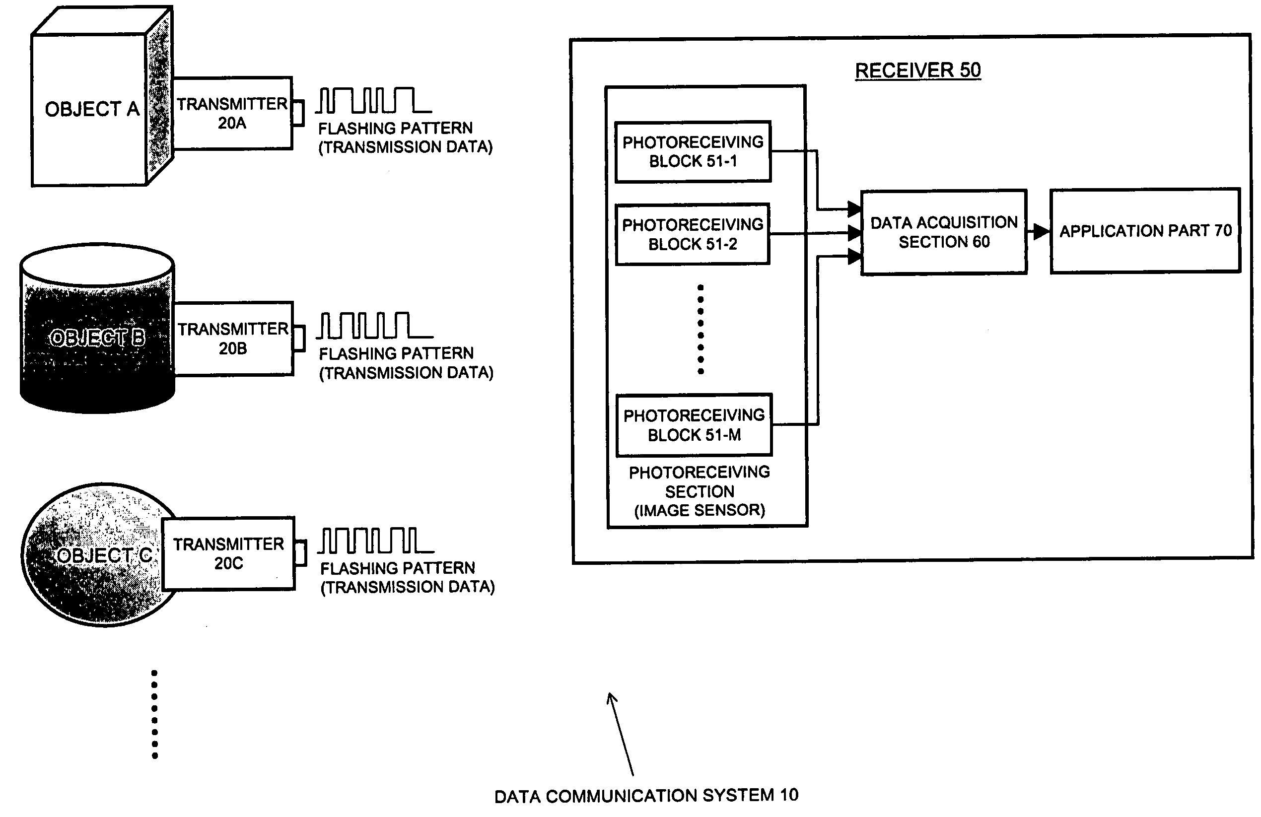
[0016]An object of the present invention is to provide a superior data communication system, a superior data transmission apparatus, and a superior data receiving apparatus that are capable of directly transferring information from a real-world object which is not connected by a communication medium.
[0017]Another object of the present invention is to provide a superior data communication system, a superior data transmission apparatus, and a superior data receiving apparatus that are capable of performing direct data transfer of information related to an object in the real world, such as the device ID, the network address, the host name, and the URL, or real-world circumstances, such as the position of the user, from an object without using a communication medium such as a wired or wireless network.
[0018]Another object of the present invention is to provide a superior data communication system, a superior data transmission apparatus, and a superior data receiving apparatus that are capable of performing robust data transfer from an object immediately in front up to an object which is comparatively far away.

Problems solved by technology

That is, from the point of view of user operation, computers are coordinated only in an indirect way, and therefore, the user operation somewhat lacks intuitiveness.
In other words, the information transmission technique based on this technique lacks robustness with respect to distance.
For example, in order to recognize a building which is far away, it would be necessary to attach a huge code on the building, and this is not practical.
That is, only an object at a very short distance can be recognized, and distant objects cannot be recognized.
Furthermore, since the single pixel receives noise and data in a mixed manner, the separation of noise and data is difficult, and a frequency filter and a wavelength filter become necessary.
Furthermore, since it is necessary to receive radio waves from a satellite, it is difficult to use it in cities and indoors.
Furthermore, it is not possible to deal with a case in which the position of the user differs from the position of the object at which information is linked, as in the case where a building is specified from a distant location.
However, in the configurations of these related arts, synchronization between the transmitter and the receiver and the wavelength division of the transmitter are necessary, and simplification of the system configuration, reduction in size, and reduction in power consumption are limited.

Method used


Image

  • Data communication system, data transmitter and data receiver
  • Data communication system, data transmitter and data receiver
  • Data communication system, data transmitter and data receiver

Examples


application example 2

E-2. Application Example 2

[0348]In uses for autonomous mobile robots, for control of parking a vehicle in a garage, etc., it is necessary to measure with high accuracy the position of a moving machine body.

[0349]When the data communication system according to this embodiment is to be applied, transmitters that generate a flashing pattern (light beacon) are arranged at a plurality of points whose positions are known in a work space. Then, a receiver is mounted on a machine body such as a robot and a vehicle, and an image of a work space is captured. When a fixed number or more of the combinations of the coordinates on the image frame and a point in the work space can be determined at the same time, the position and the inclination or the orientation of the receiver i.e., the machine body, in the work space can be calculated.

[0350]There is a meet in which small robots play soccer on a predetermined work plane such as on a desktop (e.g., “RoboCup”). In such a case, transmitters are dis...

application example 3

E-3 Application Example 3

[0352]The receiver of the data communication system according to this embodiment may be used in such a manner as to be combined with a rotation sensor such as a gyro.

[0353]In such a case, first, the absolute coordinates and the orientation are determined by the receiver, after which, by tracking the relative rotation direction by the gyro, even if the transmitter lies off the screen of the receiver, it is possible to track the transmitter by following the rotational motion.

application example 4

E-4. Application Example 4

[0354]In a general computer, a user interface formed of user input devices such as a mouse, a keyboard, etc., and a GUI (Graphical User Interface) display screen forms the basis. In contrast, in the real world-oriented interface which is also called “augmentable reality”, a desk top which is a work environment of the computer is augmented, and various objects in a real space, such as a desk, books, pencils, video cassettes, etc., in a room, can be used as input means to the computer.

[0355]One example of this augmentable reality technique includes a technique called “digital PostIt”. Normal PostIt is used to recall memories when an object is watched later by posting a memo drawn with a pen onto an object. In contrast, digital PostIt does not use physical media such as paper, but digitally links objects in the real world to data such as a memo related to the object and digitally reproduces the data.

[0356]The data communication system according to this embodim...


PUM


Abstract

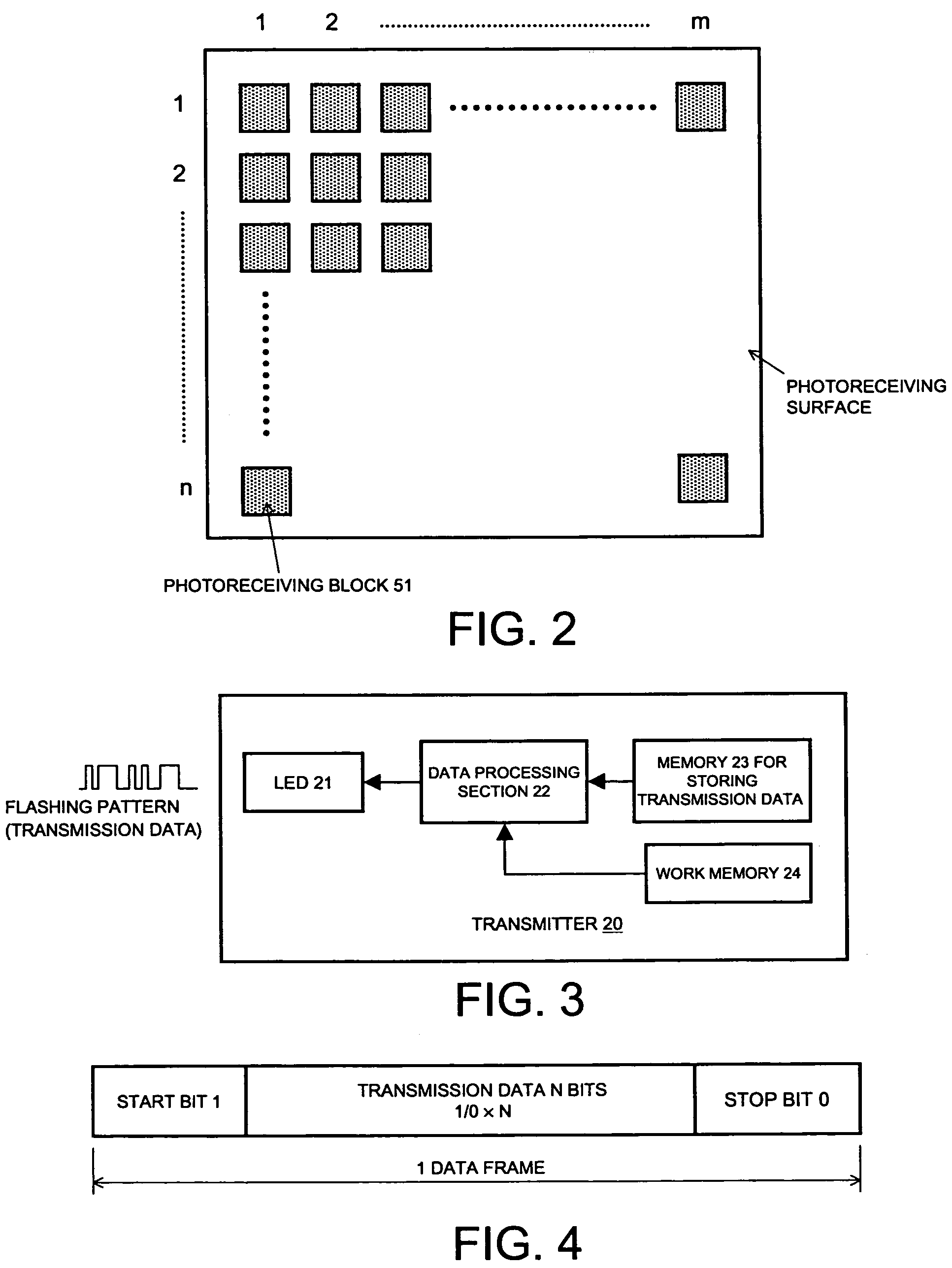
A transmitter formed of two or more light-emitting sections such as LEDs, which are physically arranged in a predetermined manner, is disposed in the real world object, and each light-emitting section transmits data by flashing at a flashing pattern representing the transmission data of a predetermined bit length. A receiver, on the other hand, includes a photoreceiving section formed from a two-dimensional photoreceiving surface, decodes the transmission data on the basis of the photoreceived flashing pattern, and recognizes the spatial information of an object on the basis of the flashing position on the two-dimensional photoreceiving surface. Therefore, information, such as an ID, can be obtained from the object in the real world, and also, the spatial position of the object can be recognized at the same time.

Description

TECHNICAL FIELD[0001]The present invention relates to a data communication system, a data transmission apparatus, and a data receiving apparatus for transferring data in a real space, and particularly, it relates to a data communication system, a data transmission apparatus, and a data receiving apparatus for performing direct data transfer of information related to an object in the real world, such as a device ID, a network address, a host name, or a URL, or the real-world circumstances such as the position of a user, from the object without using a communication medium such as a wired or wireless network.[0002]More specifically, the present invention relates to a data communication system, a data transmission apparatus, and a data receiving apparatus that are capable of performing data transfer which is robust in terms of distance, from an object immediately in front up to a comparatively distant object and, particularly, it relates to a data communication system, a data transmiss...

Claims


Application Information

Patent Timeline
IPC IPC(8): H04B10/00H04B10/11G06F3/00G06F3/033G06F3/042G06F3/048H04B10/116H04B10/118H04B10/524H04B10/54H04B10/556
CPCG06F3/002G06F3/005G06F3/0325H04B10/66G06F3/04815H04B10/1149G06F3/0481
Inventor MATSUSHITA, NOBUYUKIREKIMOTO, JUNICHITAJIMA, SHIGERUAYATSUKA, YUJIKOHNO, MICHIMUNE
Owner SONY CORP
Learn More