
Sheet cutting apparatus, sheet aftertreatment apparatus having the same, and image forming apparatus having the same

a cutting apparatus and aftertreatment technology, applied in the field of sheet cutting apparatus, sheet aftertreatment image forming apparatus having the same, can solve the problems of low operating efficiency, inability to use cutting blades for a long period of time, and variable wear, so as to reduce the number of times for replacing cutting blades.

Inactive Publication Date: 2008-08-19
COPYER
View PDF8 Cites 9 Cited by
  • Summary
  • Abstract
  • Description
  • Claims
  • Application Information

AI Technical Summary

Benefits of technology

[0009]An object of the present invention is to provide a sheet cutting apparatus which allows uniform use of the cutting blade to thereby reduce the number of times for replacing the cutting blade.
[0010]Another object of the present invention is to provide a sheet aftertreatment apparatus equipped with a sheet cutting apparatus in which the number of times for replacing the cutting blade has been reduced, thereby achieving an enhanced operating efficiency (availability ratio).
[0011]Still another object of the present invention is to provide an image forming apparatus improved in terms of productivity in image formation through provision of a sheet aftertreatment apparatus with an enhanced operating efficiency (availability ratio).

Problems solved by technology

Thus, the cutting blade is not uniformly used over its entire length but includes a portion always used for cutting regardless of the size of the sheets to be cut, and a portion not used for cutting according to the size of the sheets to be cut, resulting in a variation in wear.
Thus, the cutting blade cannot be used for a long period of time.
Further, the sheet aftertreatment apparatus equipped with the sheet cutting apparatus requires temporary suspension of after-treatment operation in order to replace the cutting blade, resulting in a rather low operating efficiency (availability ratio).
Furthermore, due to the low operating efficiency (availability ratio) of the sheet aftertreatment apparatus, the conventional image forming apparatus equipped with the sheet aftertreatment apparatus having such a sheet cutting apparatus exhibits a rather low operating efficiency (availability ratio).

Method used


Image

  • Sheet cutting apparatus, sheet aftertreatment apparatus having the same, and image forming apparatus having the same
  • Sheet cutting apparatus, sheet aftertreatment apparatus having the same, and image forming apparatus having the same
  • Sheet cutting apparatus, sheet aftertreatment apparatus having the same, and image forming apparatus having the same

Examples


Embodiment Construction

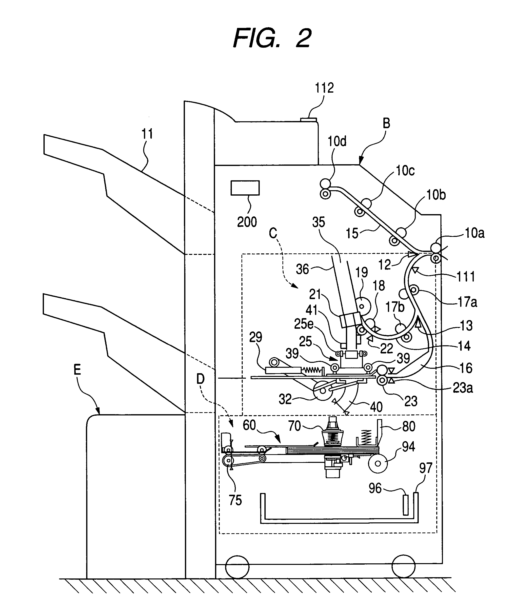
[0034]A sheet cutting apparatus according to an embodiment of the present invention, a sheet aftertreatment apparatus equipped with this sheet cutting apparatus, and copying machine constituting an example of an image forming apparatus whose apparatus main body has this sheet aftertreatment apparatus as one of its components, will be described with reference to the drawings. The values mentioned in the description of this embodiment are only given for reference purposes, and should not be construed restrictively.

[0035]The image forming apparatus may be a copying machine, a printer, a facsimile apparatus, a multifunctional apparatus composed of these apparatuses, etc. That is, the image forming apparatus is not restricted to a copying machine. Further, the sheet aftertreatment apparatus is not always provided in the apparatus main body of a copying machine. It may also be provided in the apparatus main body of a printer, a facsimile apparatus, a multifunctional apparatus composed of ...


PUM

PropertyMeasurementUnit
sizeaaaaaaaaaa
timeaaaaaaaaaa
lengthaaaaaaaaaa

Abstract

A sheet cutting apparatus including: a cutting blade for cutting a sheet to be cut, which includes a sheet or a sheet stack; and a transport devices capable of holding and rotating the sheet to be cut to cause an end portion of the sheet to be cut to be opposed to the cutting blade and transporting the sheet to be cut to a position where the end portion is cut by the cutting blade.

Description

[0001]This application claims priority benefits of Japanese Patent Application No. 2004-088005 filed Mar. 24, 2004, the entire disclosure of which is hereby incorporated herein by reference in its entirety.BACKGROUND OF THE INVENTION[0002]1. Field of the Invention[0003]The present invention relates to a sheet cutting apparatus in which a portion of a cutting blade to be used for cutting a sheet, a sheet stack, etc. is varied to make it possible to uniformly use the cutting blade, a sheet aftertreatment apparatus equipped with the sheet cutting apparatus, and an image forming apparatus whose apparatus main body has the sheet aftertreatment apparatus as one of its components.[0004]2. Related Background Art[0005]Conventionally, a sheet cutting apparatus which cuts a sheet, a sheet stack, etc. (hereinafter referred to as “sheets to be cut”) with a cutting blade is provided in a sheet aftertreatment apparatus as one of the components of the sheet aftertreatment apparatus which is provide...

Claims


Application Information

Patent Timeline
Patent Type & Authority Patents(United States)
IPC IPC(8): B41J11/70G03G15/00B26D1/08B26D5/08B26D5/16B26D7/01B26D7/02B26D7/06B26D7/18B26D7/20B65H31/34
CPCB26D1/08B26D5/16B26D7/016B26D7/025B26D7/0675B26D7/20G03G15/6582B26D7/18G03G2215/00814B26D2007/0056B26D2007/202B65H2301/4229Y10T83/8821
Inventor KIKUCHI, TOSHIKI
Owner COPYER
Learn More