
Apparatus and method for performing a loopback test in a communication system

a communication system and loopback test technology, applied in the field of communication system testing, can solve the problems of loopback testing being disrupted by the normal operation of the communication system, loopback testing wasting valuable bandwidth, and special equipment required to set up a loopback tes

Active Publication Date: 2008-08-05
ANRITSU CORP +1
View PDF40 Cites 101 Cited by
  • Summary
  • Abstract
  • Description
  • Claims
  • Application Information

AI Technical Summary

Benefits of technology

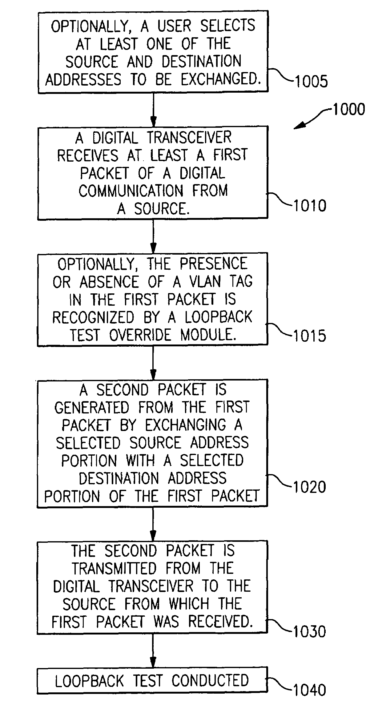
The invention is about an apparatus and method for testing digital communication systems. The apparatus includes a digital transceiver and a loopback test module. The digital transceiver receives a packet of digital communication from a source and transmits it to a destination. The loopback test module modifies the packet by exchanging the source and destination addresses and sends it back to the source for testing. The technical effect of this invention is to provide a convenient and efficient way to test the reliability and performance of digital communication systems.

Problems solved by technology

In some communication systems, setting up a loopback test requires either or both special equipment and a disruption of the normal service provided by the communication system.
In some communication systems, loopback testing can be disrupted by the normal operation of the communication system itself.
If a loop is detected, the network monitoring software (NMS) will disable the ports on which the loop was detected, as loops waste valuable bandwidth.
This means that if an apparatus, such as a test instrument, is connected that reflects frames back to the transmitter, in all likelihood, the port on which the reflector is connected will be disabled.

Method used


Image

  • Apparatus and method for performing a loopback test in a communication system
  • Apparatus and method for performing a loopback test in a communication system
  • Apparatus and method for performing a loopback test in a communication system

Examples


first embodiment

[0065]At least three embodiments or configurations are contemplated. In a first embodiment, a loop-back is caused by a piece of network equipment (NE) (e.g. spanning ports on a switch). Setup of this configuration generally requires expert knowledge of the network equipment.

second embodiment

[0066]In a second embodiment, a second CMA 5000 Gigabit Ethernet test set is provided and, runs the Reflector application described above. The advantage of this configuration is that no network knowledge is required. The CMA 5000 Reflector application will simply reflect the frames it receives. In some embodiments, no RFC measurements are made or reported on the Reflector unit.

[0067]In a third embodiment, a second CMA 5000 Gigabit Ethernet test set, running the Single Ended Network Test software, is configured as an RFC Reflector unit. The third embodiment is performed with the following setup. The test set is designated as the “Reflector” unit. A radio button is provided at the bottom of the Single Ended Network Test mode panel for this purpose. Whatever Station and Destination address information is specified for the “Transmitter” unit are reversed (or mirrored) on the “Reflector” unit. A unique gateway and network mask can be specified on each unit and each port as necessary. The...


PUM


Abstract

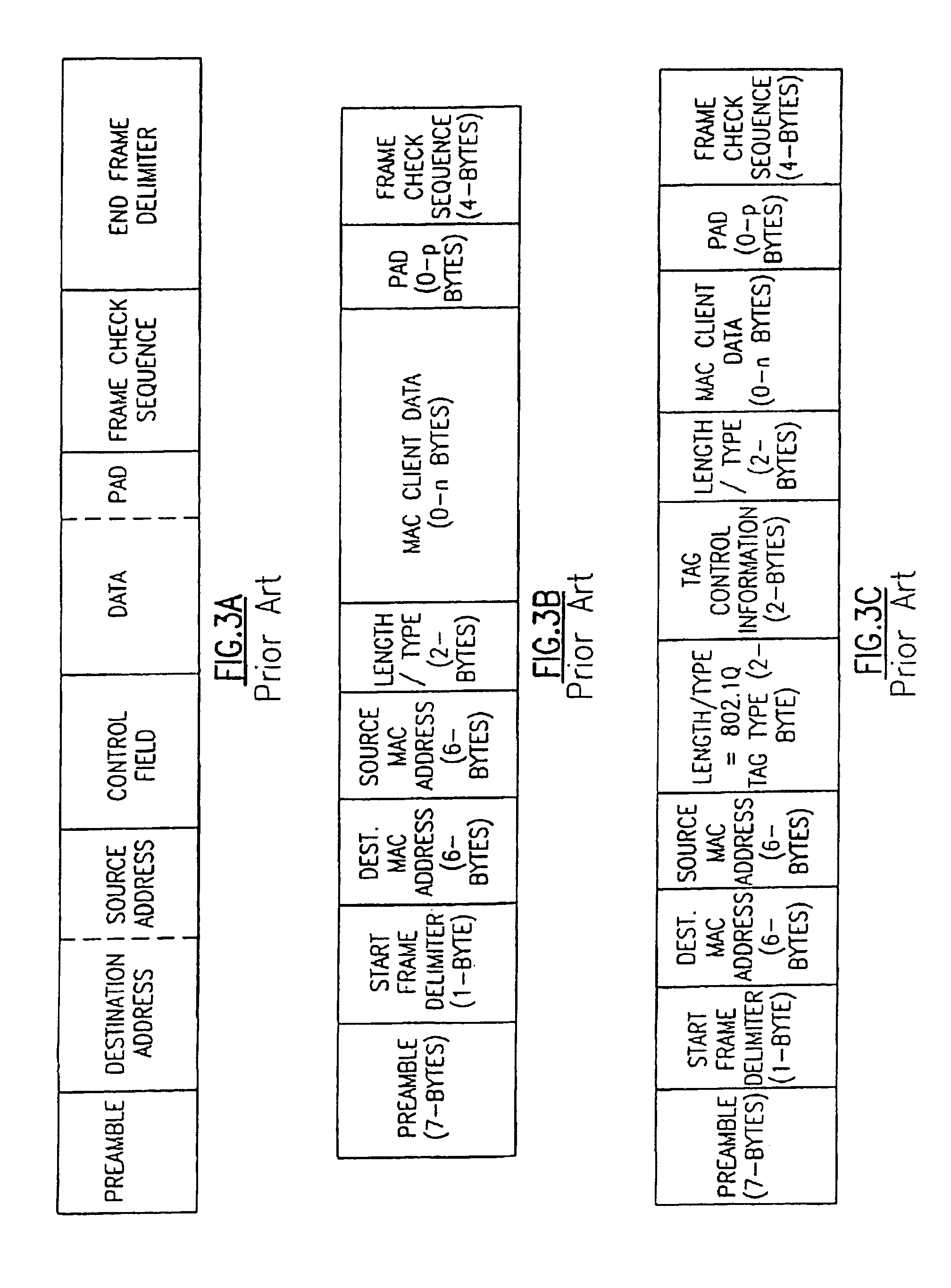
The invention is test apparatus and methods for performing loopback tests. The tests involve generating a packet-based test message having a source address and a destination address. When the test message arrives at the destination, the addresses are exchanged and the message is returned to the source. The addresses can be level 2 addresses, such as MAC addresses, and / or level 3 addresses, such as IP addresses. The returned message and the propagation properties observed for the test message can be used to determine information about the network being tested.

Description

FIELD OF THE INVENTION[0001]The invention relates to testing in communication systems in general and particularly to a communication system that employs packets having addresses for performing loopback testing.BACKGROUND OF THE INVENTION[0002]Loopback testing is a well known technique for examining the operational characteristics of communication systems. In a loopback test, a message is transmitted from a source and traverses some portion of a communication system, ultimately returning to the source. Upon the return of the message, the information content of the message and / or the physical attributes of the message (e.g., signal strength, signal-to-noise ratio, and other parameters of interest) can be observed and compared to the same information and / or parameters as they existed when the message was initially transmitted. Information about the state of the portions of the communication system that the message traversed and indications of the quality of service that is being provid...

Claims


Application Information

Patent Timeline
Patent Type & Authority Patents(United States)
IPC IPC(8): H04L1/24
CPCH04L1/243H04L43/50H04L12/4645H04L12/2697
Inventor DERAGON, AARON THOMASSOULE, GREGORY JOHN
Owner ANRITSU CORP
Learn More