
Wireless communication system for monitoring physical downlink control channel

a communication system and control channel technology, applied in multiplex communication, orthogonal multiplex, frequency-division multiplex, etc., can solve the problems of difficult detection of control information, inability to decode user data on a data channel, and increase in the number of decoding attempts in the control region on which the control information is transmitted, so as to reduce the number of decoding attempts

Active Publication Date: 2009-04-02
LG ELECTRONICS INC
View PDF19 Cites 572 Cited by
  • Summary
  • Abstract
  • Description
  • Claims
  • Application Information

AI Technical Summary

Benefits of technology

[0009]A method is sought for monitoring a control channel in order to reduce the number of decoding attempts in blind decoding. In one embodiment of the present invention, a method of monitoring a physical downlink control channel (PDCCH) in a wireless communication system includes monitoring a set of PDCCH candidates for a search space in a subframe, wherein the subframe includes a control region for transmitting control information, the control region including a plurality of resource elements mapped to a plurality of control channel elements (CCEs), a CCE corresponds to a set of resource elements, and the search space that includes a contiguous set of CCEs is classified into a common search space and a UE-specific search space, wherein the common search space is monitored by all user equipments (UEs) in a cell and the UE-specific search space is monitored by at least one UE in the cell.

Problems solved by technology

If the user equipment does not properly detect its control information from the multiplexed control information, it may not decode user data on a data channel.
However, it may be difficult to detect the control information only by the simple blind decoding when different control information is necessary for different user equipments and control information of each user equipment has different code rate and modulation scheme.
Accordingly, the number of decoding attempts in a control region on which the control information is transmitted may unexpectedly increase.
As the number of decoding attempts in the blind decoding increases, battery consumption will also increase.

Method used


Image

  • Wireless communication system for monitoring physical downlink control channel
  • Wireless communication system for monitoring physical downlink control channel
  • Wireless communication system for monitoring physical downlink control channel

Examples


Embodiment Construction

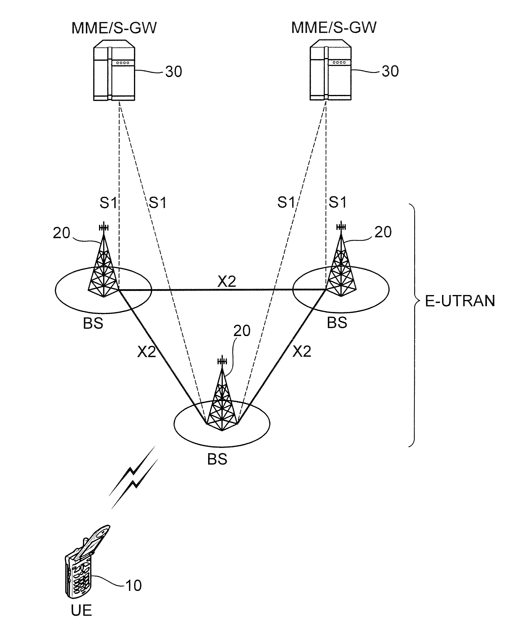
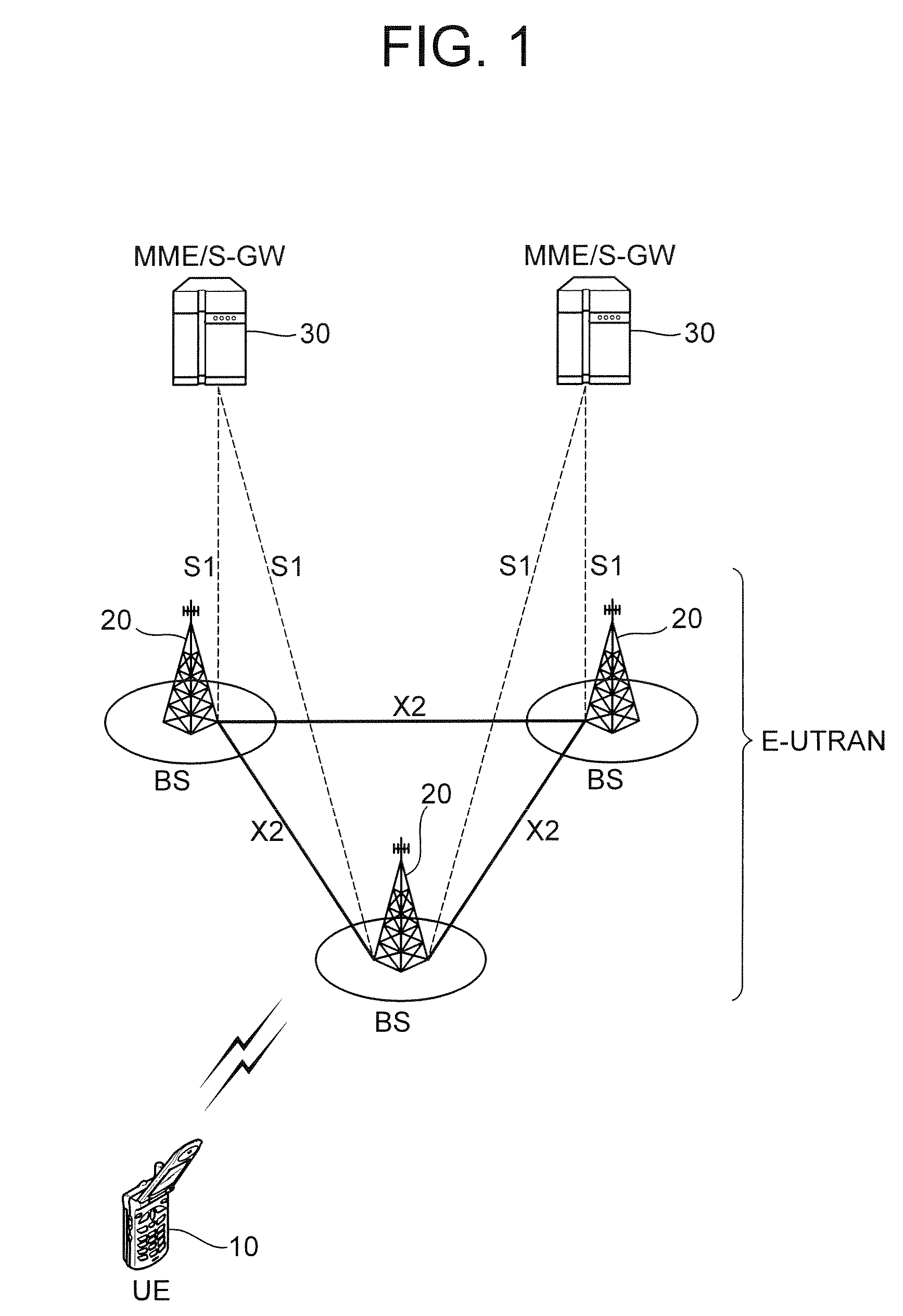
[0037]FIG. 1 is a block diagram showing a wireless communication system. The wireless communication system may be a network structure of an E-UMTS (Evolved-Universal Mobile telecommunications System) which is also referred to as an LTE (Long-Term Evolution) system. The wireless communication system may provide a wide variety of communication services including voices and packet data.

[0038]Referring to FIG. 1, an E-UTRAN (Evolved-UMTS Terrestrial Radio Access Network) includes at least one base station (BS) 20. A user equipment (UE) 10 can be fixed or mobile. The UE 10 may also be referred to as an MS (Mobile Station), a UT (User Terminal), a SS (Subscriber Station), or a wireless device. Generally, the BS 20 is a fixed station that communicates with the UE 10 and may also be referred to as an e-NB (evolved-NodeB), a BTS (Base Transceiver System), or an access point. There are one or more cells within the coverage of the BS 20. Interfaces for transmitting user traffic or control traf...


PUM


Abstract

A method of monitoring a physical downlink control channel (PDCCH) in a wireless communication system is provided. A user equipment monitors a set of PDCCH candidates for a search space in a subframe. The search space includes a common search space monitored by all user equipments in a cell and a UE-specific search space monitored by at least one UE in the cell.

Description

CROSS-REFERENCE TO RELATED APPLICATIONS[0001]Pursuant to 35 U.S.C. § 119(a), this application claims the benefit of earlier filing dates and right of priority to U.S. Provisional Application No. 60 / 976,140, filed on Sep. 28, 2007, U.S. Provisional Application No. 61 / 023,440, filed on Jan. 25, 2008, U.S. Provisional Application No. 61 / 033,725, filed on Mar. 4, 2008, U.S. Provisional Application No. 61 / 045,970, filed on Apr. 18, 2008, and Korean Application No. 10-2008-0090742, filed on Sep. 16, 2008, the contents of which are hereby incorporated by reference herein in their entirety.FIELD OF THE INVENTION[0002]The present invention relates to a wireless communication system and a method of monitoring a physical downlink control channel in the wireless communication system.DESCRIPTION OF THE RELATED ART[0003]In a wireless communication system, a base station (BS) provides services to a plurality of user equipments (UEs). The base station schedules user data for the plurality of user e...

Claims


Application Information

Patent Timeline
IPC IPC(8): H04W24/00H04L27/28
CPCH04L1/0029H04L1/0032H04L5/00H04L27/2613H04L5/0053H04L1/0061H04L5/0007H04L5/0037H04L27/2666H04W48/16H04W76/28H04W76/27H04W24/00H04J2211/005H04B2201/70724
Inventor CHUNG, JAE HOONKIM, SO YEONLEE, EUN JONG
Owner LG ELECTRONICS INC
Learn More