
Method and apparatus for an on-chip variable acuity imager array incorporating roll, pitch and yaw angle rates measurement

Inactive Publication Date: 2008-08-05
TELEDYNE SCI & IMAGING
View PDF10 Cites 32 Cited by
  • Summary
  • Abstract
  • Description
  • Claims
  • Application Information

AI Technical Summary

Benefits of technology

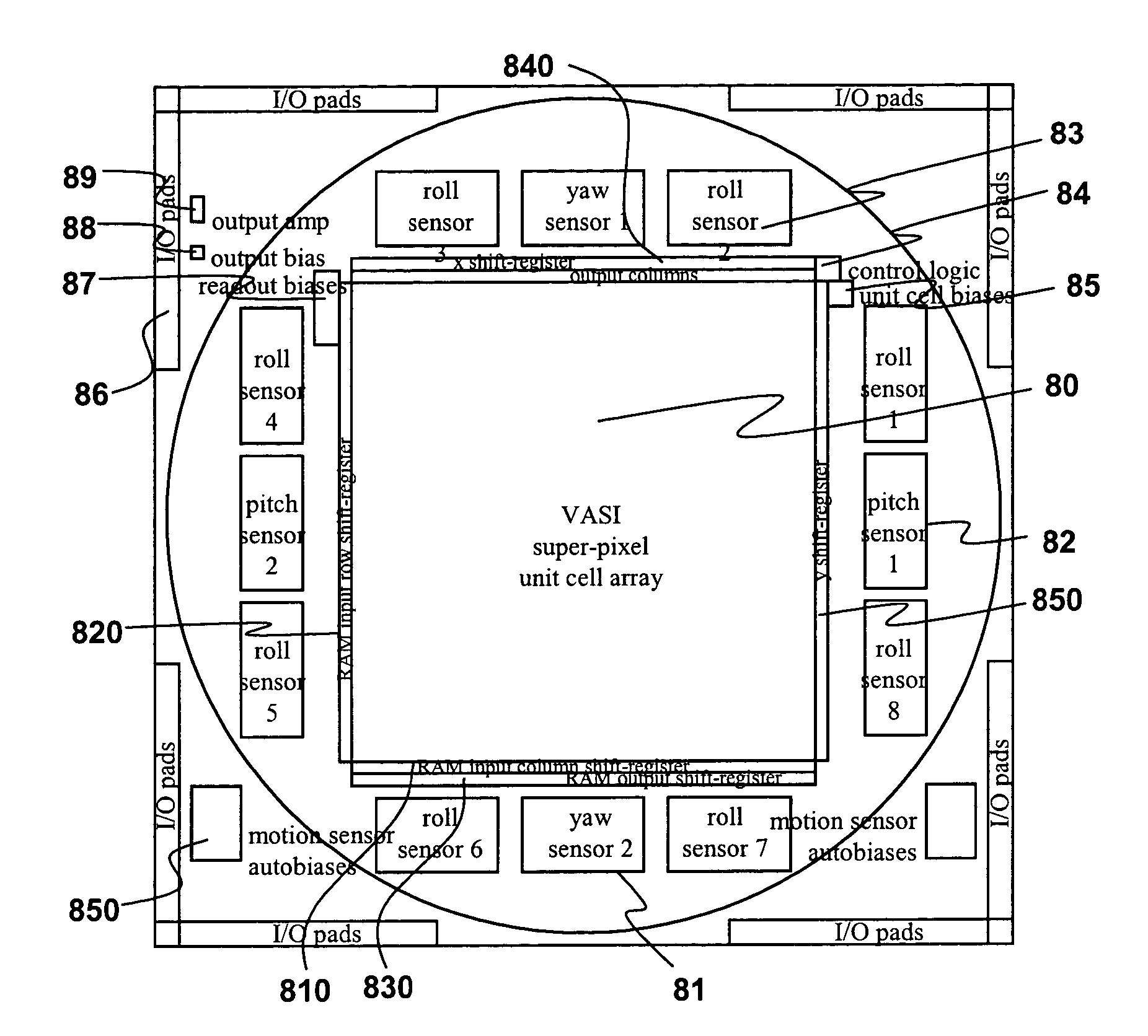
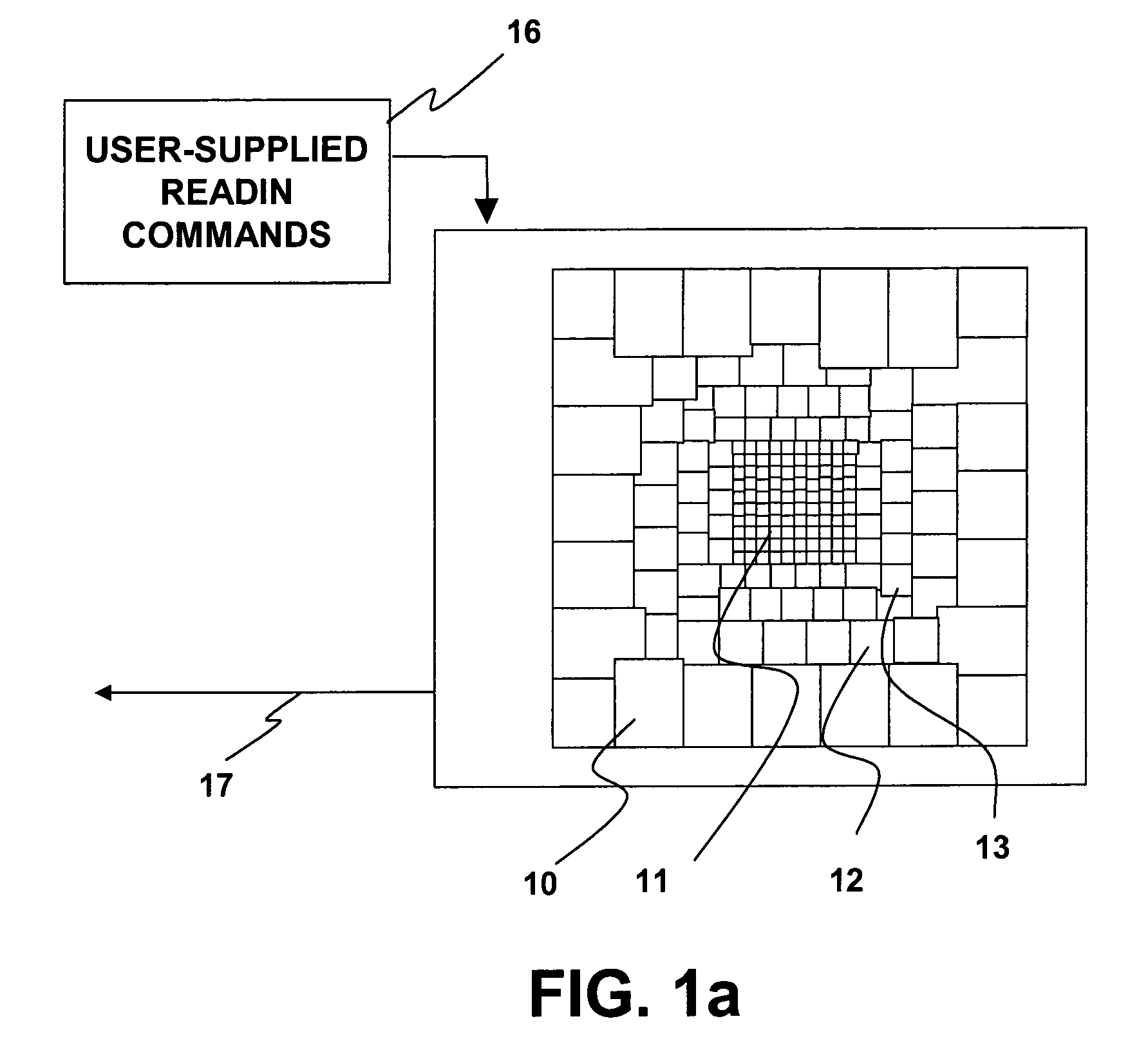
[0009]The imager of the present invention consists of two subsystems, the “Variable Acuity Superpixel Imager” (VASI) subsystem and the “Yaw Pitch Roll” (YPR) subsystem. The VASI subsystem provides a means for very high-speed two-dimensional imaging of the complete field-of-view with the capability of retaining the highest possible

Problems solved by technology

Sensing high spatial resolution imagery at very high frame rates, covering wide fields of view while at the same time producing a low data bandwidth so as not to overload data transmission “pipes” is problematic in current imaging systems.
In addition, spatial agglomeration of pixel values in Fossum's implementation is performed in the column region of the integrated circuit imposing a speed limitation on the number of frames per second which may be produced because all analog pixel values must be shifted out of the unit cell region before such pixel combination is performed.

Method used


Image

  • Method and apparatus for an on-chip variable acuity imager array incorporating roll, pitch and yaw angle rates measurement
  • Method and apparatus for an on-chip variable acuity imager array incorporating roll, pitch and yaw angle rates measurement
  • Method and apparatus for an on-chip variable acuity imager array incorporating roll, pitch and yaw angle rates measurement

Examples


Embodiment Construction

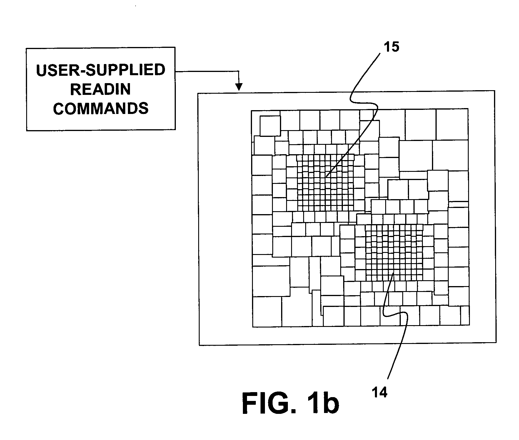
[0024]The present invention provides an imaging system solving the problem of transmitting on the “most important” aspects of the image while retaining the essential information contained in the rest of the image. “Variable Acuity Superpixel Imaging” (VASI) technology, the subject of this invention, provides selected imaging and motion-analysis functions comparable to the human retina to be able to report analog signals representative of regions within the image requiring high spatial resolution sampling as well as image-based pitch, yaw and roll angle rates.

[0025]A system employing the present invention permits complete freedom with respect to the spatial agglomeration of pixels on the imaging device without limitation to number and size of image regions which may be so configured. Further, performance of such spatial agglomeration processing within each unit cell in a massively parallel fashion combined with intelligent means for fast spatial configuration is desirable such that t...


PUM


Abstract

A variable acuity imager incorporates an array of detection elements for light energy, in the visible, infrared, ultraviolet, or light energy in another region of the electromagnetic spectrum with a means to change the spatial configuration of the array to include “superpixels” by combining energy detected by adjacent elements, thus permitting any number of high-resolution “foveal” regions to be placed within the confines of the focal plane array and moved around at the frame rate of the imaging device. Detectors to measure the pitch, yaw and roll angle rates of background imagery using velocity-sensing circuitry are employed for variation of the foveal regions to accommodate motion of the array.

Description

CROSS-REFERENCE TO RELATED APPLICATIONS[0001]This application claims priority of the Provisional Application serial No. 60 / 394,031, filed on Jul. 6, 2002, having a title of “VARIABLE ACUITY IMAGER WITH ON-CHIP ROLL / PITCH / YAW ANGLE RATE SENSING”.STATEMENT REGARDING FEDERALLY SPONSORED RESEARCH[0002]This invention was conceived and / or reduced to practice in conjunction with Air Force Research Laboratory, Eglin AFB contract no. F08630-00-C-0018.BACKGROUND OF THE INVENTION[0003]1. Field of the Invention[0004]This invention relates generally to the field of focal plane imaging devices and, more particularly, to an imaging system employing variable acuity super-pixel imaging that also provides analog signals representative of pitch, roll and yaw angle rates by image motion analysis.[0005]2. Description of the Related Art[0006]Sensing high spatial resolution imagery at very high frame rates, covering wide fields of view while at the same time producing a low data bandwidth so as not to ove...

Claims


Application Information

Patent Timeline
IPC IPC(8): H04N5/228H04N5/225H04N5/374
CPCH04N5/335H04N3/155H04N25/76H04N25/443H04N25/00
Inventor BAXTER, CHRISTOPHER ROBERTETIENNE-CUMMINGS, RALPH ROCHMASSIE, MARK ALANCURZAN, JON PAUL
Owner TELEDYNE SCI & IMAGING
Learn More