
Method and system for charging a NiMH or NiCd battery

Inactive Publication Date: 2008-07-29
SCHNEIDER ELECTRIC IT CORP
View PDF1 Cites 16 Cited by
  • Summary
  • Abstract
  • Description
  • Claims
  • Application Information

AI Technical Summary

Benefits of technology

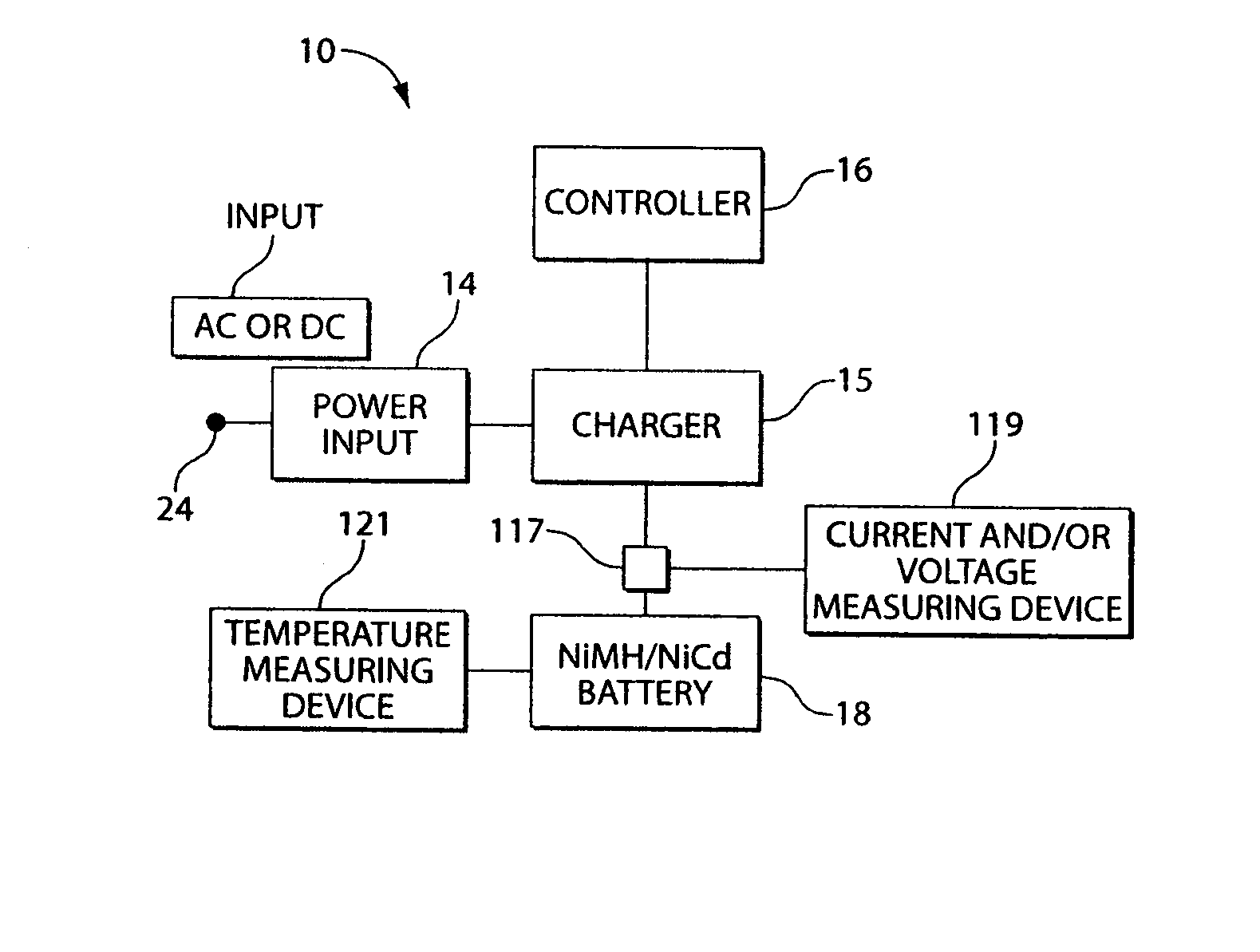
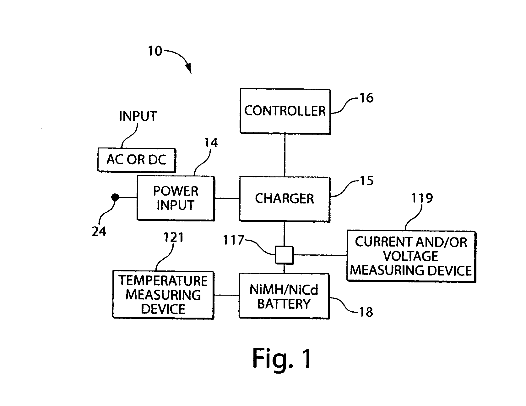
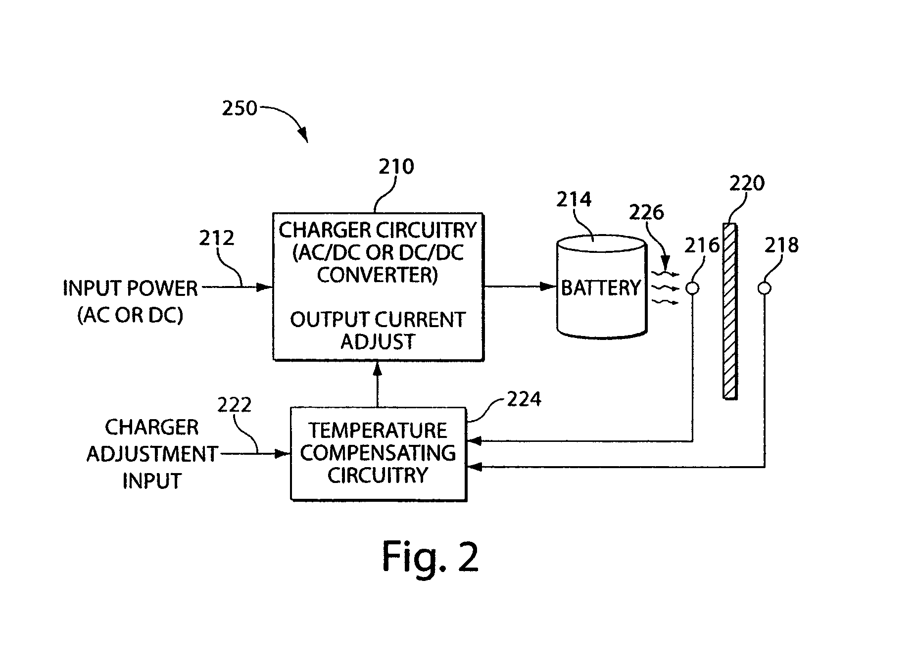
[0008]It is desirable to have a method of charging a NiMH or NiCd battery such that charging does not occupy a substantial amount of time and such that the overall operating temperature of the battery during use and especially charging is reduced during the lifetime of the battery, thereby extending the life of the battery. This invention is directed to a method of charging that is accomplished using a temperature differential method to continuously regulate the rate of charge injected into the battery. An amplifier is used to amplify the detected or sensed difference in temperature between the one or more cases in which the battery or batteries are contained and ambient temperature. In this method, the greater the difference in temperature, the lower the charging current is injected into the battery.
[0010]In general, in another aspect, the invention is directed to a method of charging a battery. The method of charging comprises detecting at least one battery, sensing a first temperature at a point proximal to the battery, sensing a second temperature at a point distal to the battery, and controlling current into the battery according to a difference between the first temperature and the second temperature. The invention provides one or more of the following advantages. The charging method of the invention improves the electrical efficiency of the charge process as the battery is charged to a 100% state of charge as quickly as the battery can accept charge. One hundred percent SOC is maintained in the battery without overheating the cells of the battery and by matching the rate of self-discharge with changes based on the battery age and ambient conditions. The consistency of charge rates is increased without computations with a microprocessor or other digital means. Eliminating the need for microprocessors in chargers implementing the battery charging method reduces the cost associated with a charger. Further, charging batteries according to the method of the invention increases safety by reducing a dependency on complex algorithms using voltage, temperature, and / or rate of charge of the batteries.
[0011]An uninterruptible power supply (USP) system used with the charging system of the present application includes one or more NiMH or NiCd batteries. NiMH and NiCd battery chemistries are desirable because they are respectively about 2 and 5 times volumetrically and gravimetrically more energy dense than an equivalent lead acid battery that is typically used in a UPS. Thus, the size of an NiMH or NiCd battery is much smaller and lighter than a similarly performing lead acid battery and makes the product into which it is installed more attractive, versatile and useful to customers. The extra volume required by similarly performing lead acid batteries typically requires extra floor space and costly hardware to install the batteries.
[0012]Another advantage of both NiMH and NiCd batteries is that they are relatively temperature immune. Their performance suffers little at the extremes of the lead acid limits, and their lifetime is not affected as dramatically by temperature as are lead acid batteries. It has been estimated that NiMH battery life times are around 10-15 years. Lead acid batteries can be designed to last similarly long, but compromise their energy density doing so.

Problems solved by technology

The extra volume required by similarly performing lead acid batteries typically requires extra floor space and costly hardware to install the batteries.

Method used


Image

  • Method and system for charging a NiMH or NiCd battery
  • Method and system for charging a NiMH or NiCd battery
  • Method and system for charging a NiMH or NiCd battery

Examples


example

By way of example if,

[0053]Vb is 1.5V (typical for one cell),

[0054]Rs is 0.11 (typical of a small battery size),

[0055]Zth is 10° C. / Watt (a function of the placement of the probes)

[0056]Set Td to 0.2° C. (by controlling the reference voltage to the amplifier).

To determine the steady-state overcharge charge maintenance current, use equation (14):

[0057]Iocv=TdVb×Zth=13⁢mA(14)

and according to equation (6),

Pdiss=(Io2×Rs)+(Iocv×Vb)=20 mW  (6)

20 mW of heat is generated by the excessive charge current in the battery during the float charging mode. This is a small and manageable amount of heat resulting in only a 0.2° C. rise in the battery above ambient.

To determine the full charging current at the beginning of the charge cycle, use (12):

[0058]Io=TdRs×Zth=0.45⁢A(12)

and the internal Pdiss is also,

Pdiss=(Io2×Rs)+(Iocv×Vb)=20 mW  (6)

By fixing the measured temperature differential, ΔT, to Td, the internal energy dissipation rate is held to a fixed value no matter what the battery's state of ch...


PUM


Abstract

A method of charging a NiMH or NiCd battery such that charging does not occupy a substantial amount of time and such that the operating temperature of the battery is reduced during the lifetime of the battery, thereby extending the life of the battery. This invention is a method of charging that is accomplished using a temperature differential method to continuously regulate the rate of charge injected into the battery. An amplifier is used to amplify the difference in temperature between one or more cases in which the battery is contained and ambient temperature. In this method, the greater the difference in temperature, the lower the charging current is injected into the battery. The method of charging may be incorporated into uninterruptible power supply equipment.

Description

CLAIM OF PRIORITY TO PRIOR APPLICATIONS[0001]This application is a continuation of U.S. patent application Ser. No. 10 / 639,819, filed Aug. 13, 2003 now U.S. Pat. No. 7,129,676, which is a continuation in part of U.S. patent application Ser. No. 09 / 838,753, filed Apr. 19, 2001 now abandoned, the disclosure of which is incorporated herein by reference.FIELD OF THE INVENTION[0002]The present application relates generally to a system containing rechargeable batteries and a method for recharging them when they become discharged. More specifically, the present application relates to a novel method of recharging NiMH and NiCd Batteries and maintaining their state of charge between discharges. Such batteries may be incorporated into an uninterruptible power supply (UPS) to ensure power availability for critical and / or sensitive loads, as disclosed with respect to NiMH batteries in application Ser. No. 09 / 838,753.BACKGROUND OF THE INVENTION[0003]When a NiCd battery or NiMH battery is fully c...

Claims


Application Information

Patent Timeline
IPC IPC(8): H01M10/44H01M10/46H02J9/06
CPCH02J9/062
Inventor HOFF, C. MICHAELNELSON, JAMES E.
Owner SCHNEIDER ELECTRIC IT CORP
Learn More