Method and device for adjusting a laser

a laser and laser slope technology, applied in semiconductor lasers, distance measurement, instruments, etc., can solve the problems of low laser current, low laser slope, and high curren

Inactive Publication Date: 2008-07-22
II VI DELAWARE INC
View PDF6 Cites 1 Cited by
  • Summary
  • Abstract
  • Description
  • Claims
  • Application Information

AI Technical Summary

Benefits of technology

[0026]This method enables the differential current to be regulated without having to explicitly measure the threshold current.

Problems solved by technology

1. In order that the laser achieves a sufficient modulation bandwidth, IBIAS-Ith, i.e. the difference between the bias current and the threshold current of the laser, has to be chosen to be relatively high, for example 30 to 50 mA, thereby already resulting in relatively high laser currents. With increasing temperature and aging, the laser slope decreases and the threshold current rises. In the case of regulation to constant power, the reduced laser slope has to be compensated for by a significant increase in the laser current.
This may very rapidly lead to the maximum available or permissible laser current being exceeded.
Moreover, a very large modulation amplitude Imod is then necessary for a constant extinction ratio, which in turn is difficult to achieve at high data rates and furthermore leads to undesirable relaxation oscillations at the high level “1”.
Although this can be compensated for by increasing the modulation current Imod, an aging-dictated change in the extinction ratio ER is generally unavoidable.
However, a high extinction ratio disadvantageously leads to a high degree of relaxation oscillations of the laser.
2. The regulation to constant power is relatively inaccurate since the ratio of detector current of the monitor diode to the power in the fiber changes with respect to temperature and to aging.

Method used


Image

  • Method and device for adjusting a laser
  • Method and device for adjusting a laser
  • Method and device for adjusting a laser

Examples


Embodiment Construction

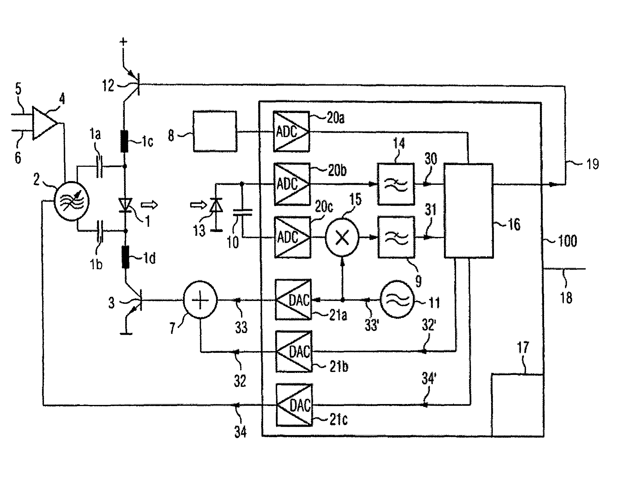
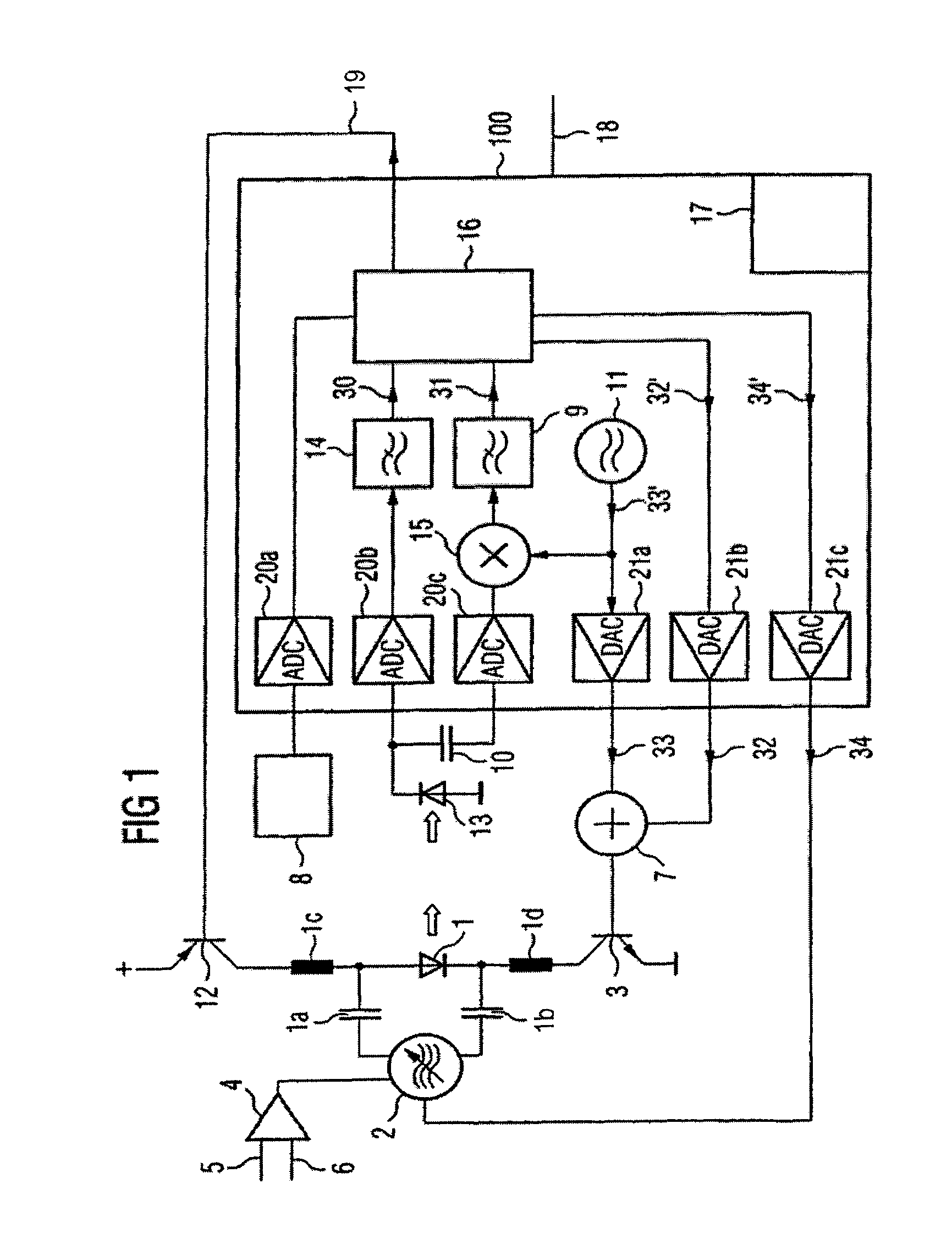
[0033]In accordance with FIG. 1, a laser diode 1 is coupled to a monitor diode 13 via an optical connection. An optical signal emitted by the laser diode 1 is transmitted partly to the monitor diode 13 via the optical coupling and converted into an electrical monitor signal, for example a monitor current. Furthermore, the laser diode is thermally coupled to a temperature sensor 8, which converts the present temperature of the laser diode into an electronic signal.

[0034]The monitor diode 13 and the temperature sensor 8 are connected to a microcontroller 100, which evaluates the electrical signals. The microcontroller 100 additionally has analog and digital control outputs operatively connected to peripheral elements of the laser diode 1. The microcontroller 100 controls a PNP switching transistor 12 via the control line 19, so that the laser current of the laser diode 1 can be switched off by means of this safety circuit in the case of overheating.

[0035]The laser current that can be ...


PUM


Abstract

The aim of the invention is to adjust the operating point of a laser that can be modulated by a data signal. The operating point of the laser is adjusted by regulating a direct current flowing through the laser; whereby said direct current correlates with the optical characteristics of the laser. In order to carry out said adjustment, the direct current is controlled above an alterable threshold current. A differential current defined from the difference between the direct current and the threshold current or a variable correlating with the differential current is adjusted to a constant value or one that is solely dependent on temperature for the adjustment of said operating point.

Description

RELATED APPLICATION[0001]This application claims priority to and incorporates by reference International Application No. PCT / DE01 / 03468 filed Sep. 5, 2001, which is entitled “Method and Device for Adjusting a Laser”, which claims priority to German patent application serial no. 101 38 474.2 filed on Aug. 3, 2001, which were not published in English, and which are both hereby incorporated by reference in their entirety.FIELD OF THE INVENTION[0002]The invention relates to a method and a device for regulating a laser.BACKGROUND OF THE INVENTION[0003]U.S. Pat. No. 5,850,409 discloses feeding back measurement signals, converted by means of a monitor diode, for regulating the laser power and the output amplitude of the modulated optical data. In this case, a pilot tone is superposed on a data signal, said pilot tone having a relatively low frequency and a low amplitude compared with the data signal. The output amplitude of the modulated data is regulated to a constant value. For this purp...

Claims


Application Information

Patent Timeline
Patent Type & Authority Patents(United States)
IPC IPC(8): H01S3/00H01S5/042H01S5/06H01S5/0683
CPCH01S5/06832H01S5/0427H01S5/0617
Inventor AURACHER, FRANZSCHOLZ, ROBERT
Owner II VI DELAWARE INC
Why Eureka
Try Eureka