
Switch stalk device

a technology of switch stalk and switch plate, which is applied in the direction of contact mechanism, contact operating parts, transportation and packaging, etc., can solve the problems of affecting the inability to make the housing or the lever support small and thin, and the inability to reduce the reliability of the etc., to achieve compactly received, small housing or the lever support can be made thin and easy to use

Inactive Publication Date: 2008-07-22
ALPS ALPINE CO LTD
View PDF10 Cites 2 Cited by
  • Summary
  • Abstract
  • Description
  • Claims
  • Application Information

AI Technical Summary

Benefits of technology

The invention is a stalk switch device that includes an operating lever, a lever support, a housing, and a circuit board. The device has a unique design that allows for efficient contact switching even when the operating lever is tilted. The device includes first and second sliders that rotate in an interlocking manner to perform the switching operation. The design of the sliders allows for a sufficient amount of movement for the contact switching part of the second slider, even when the amount of rotational movement of the driven part of the first slider is small. The housing or lever support can be made small and thin without being hindered. The technical effects of the invention are efficient contact switching, compact design, and ease of operation.

Problems solved by technology

However, when the operating lever is tilted with respect to the lever support (for example, at the time of beam switching operation), the operation plane of the operating lever is substantially orthogonal to the circuit board, and the driving part that is provided in the operating lever so as to protrude therefrom cannot be moved along the circuit board at the time of operation.
Such design constraint became a factor that the housing or lever support is hindered from being made small and thin.
In addition, if the amount of movement of the slider needed for the switching operation of the contact is not sufficient, degradation of reliability degradation, or increase in cost will be inevitably entailed.

Method used


Image

  • Switch stalk device
  • Switch stalk device
  • Switch stalk device

Examples


Embodiment Construction

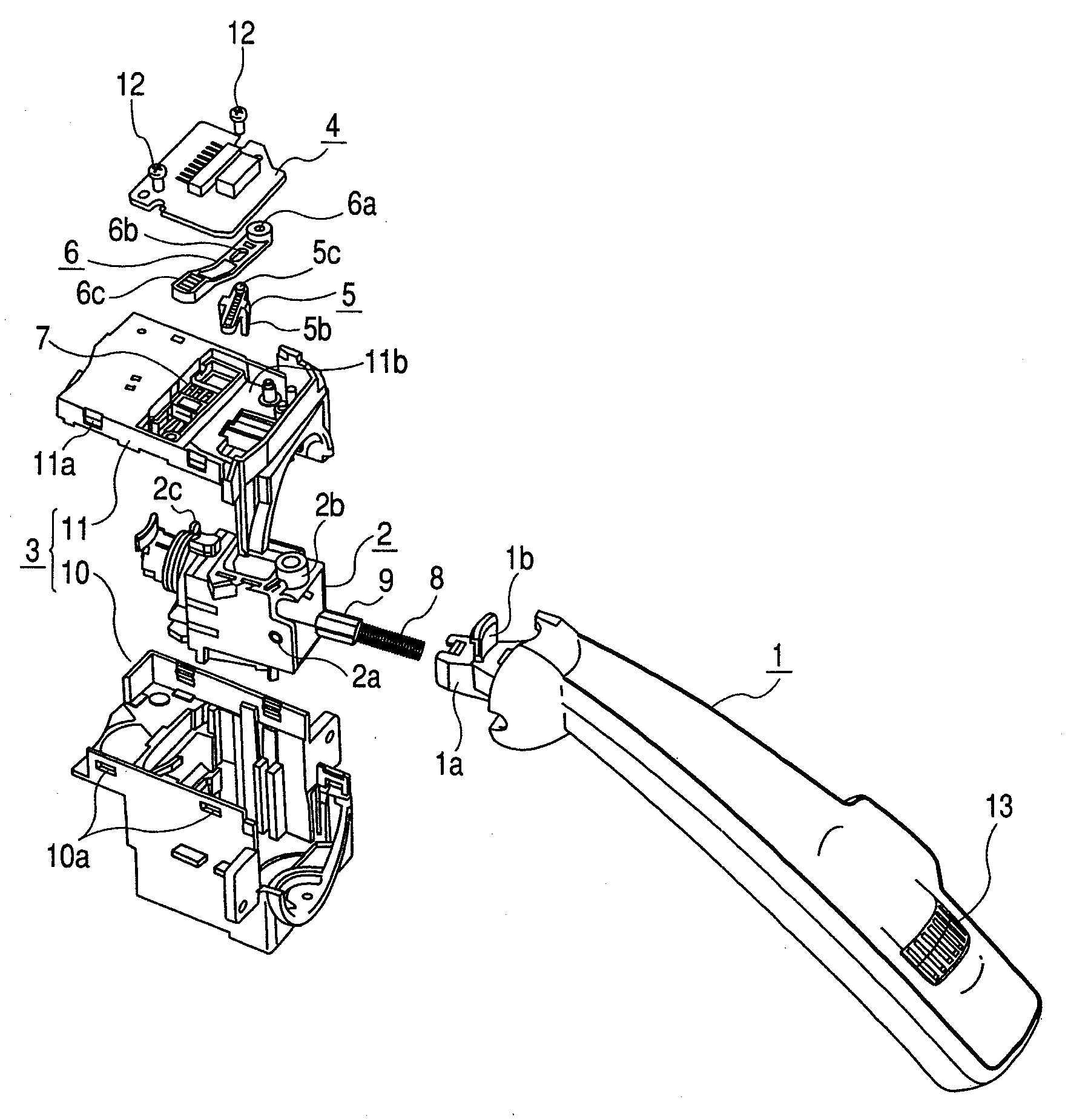
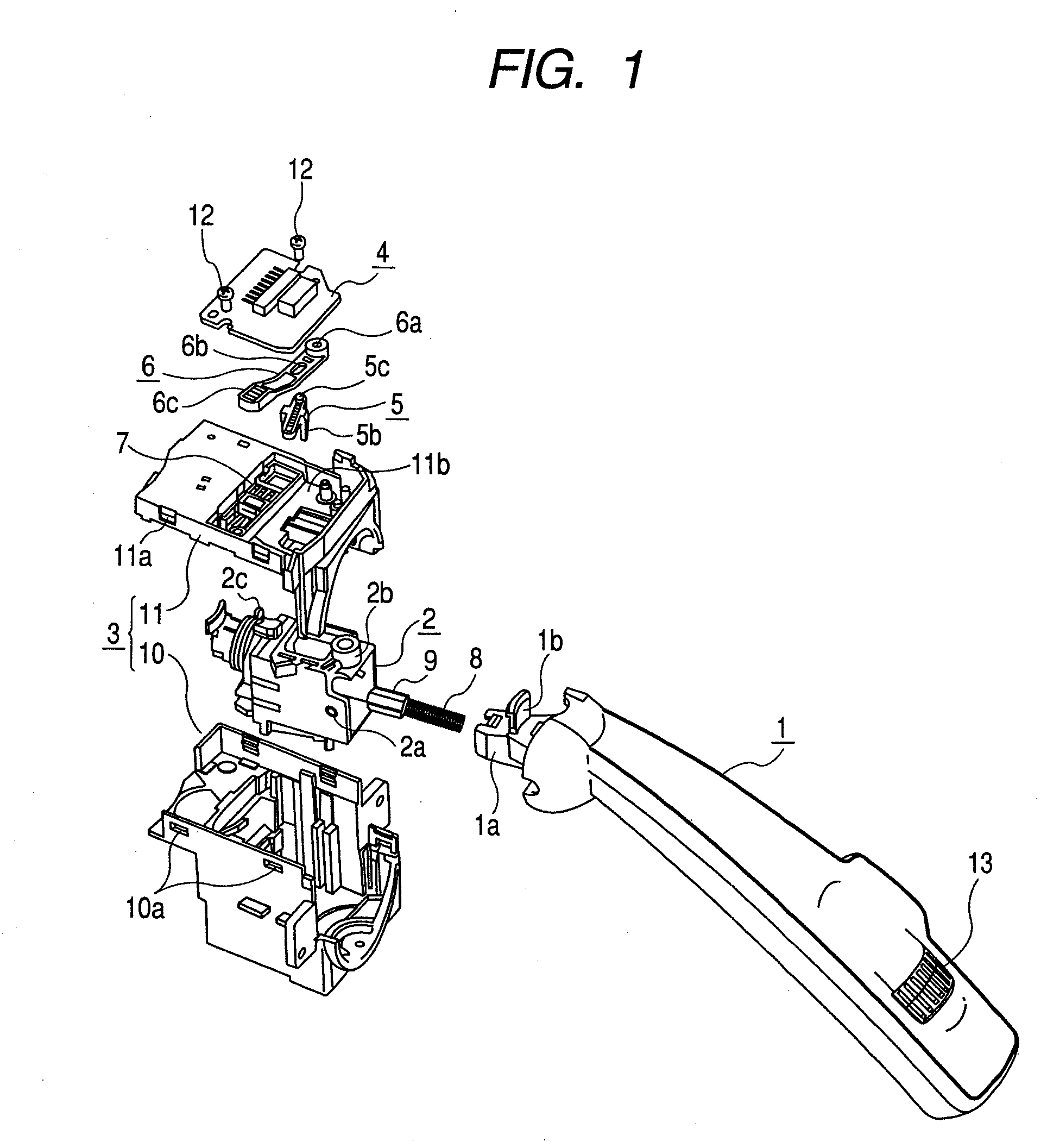
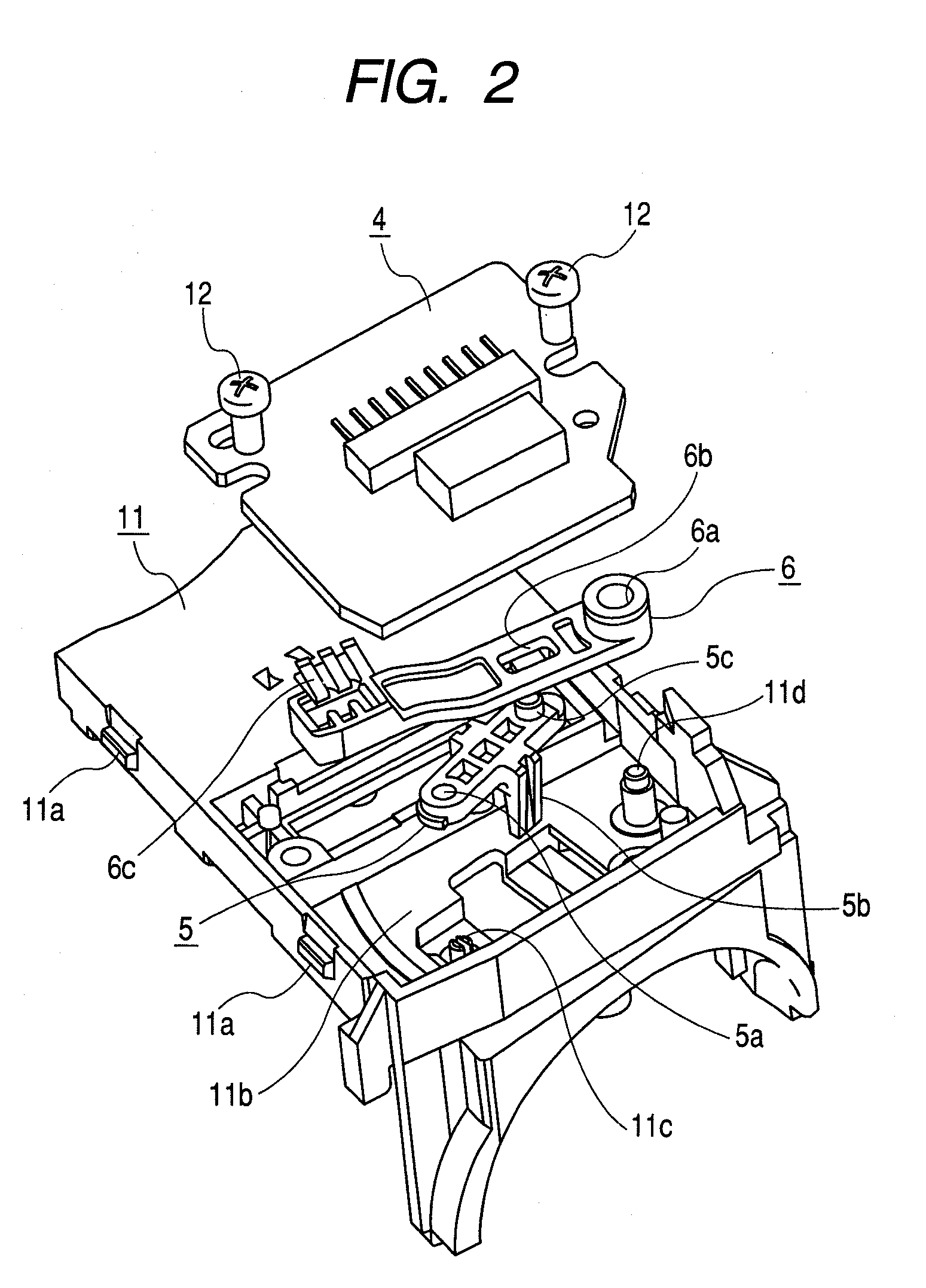
[0019]An embodiment of the invention will be described with reference to the accompanying drawings in which FIG. 1 is an exploded perspective view of a stalk switch device according to an embodiment, FIG. 2 is an exploded perspective view showing principal parts of FIG. 1 in an enlarged manner, FIG. 3 is a plan view of the principal parts showing the engagement between a pair of sliders provided in the stalk switch device at the time of non-operation thereof; FIG. 4 is a side view of the principal parts corresponding to FIG. 3, FIG. 5 is a plan view of the principal parts showing the engagement between the sliders of the stalk switch device during tilting operation thereof; and FIG. 6 is a side view of the principal parts corresponding to FIG. 5.

[0020]A stalk switch device shown in these drawings mainly includes an operating lever 1, a lever support 2 that receives and tiltably supports a base 1a of the operating lever 1, a housing 3 that receives and tiltably supports the lever sup...


PUM


Abstract

A thin film magnetic head includes a recording and playback element, a lead conductor layer for feeding a power to the recording and playback element, an electrically conductive bump for conductively connecting the lead conductor layer to an electrode pad for external connection, and an insulating protective layer filling between the recording and playback element and the electrically conductive bump. A thermal deformation-preventing layer composed of a material having a thermal expansion coefficient smaller than that of the insulating protective layer is disposed in the insulating protective layer in such a way as to locate between a medium-facing surface and the electrically conductive bump without being exposed at the medium-facing surface. In the resulting thin film magnetic head, protrusion of the recording and playback element toward the recording medium side can be prevented without changing the configuration of the recording and playback element nor the forming material.

Description

RELATED APPLICATIONS[0001]This application claims the benefit of Japanese Patent Application No. 2006-248135, filed on Sep. 13, 2006, the entire contents of which is hereby incorporated by reference.BACKGROUND[0002]1. Field of the Invention[0003]The present invention relates to a stalk switch device that is provided near a steering wheel of an automobile and used for beam switching operation, turn signal operation, etc.[0004]2. Description of the Related Art[0005]Generally, a pair of stalk switch devices is disposed on both sides of a housing fixed to a steering column, etc., thereby constituting a combination switch. Each of the stalk switch devices is tiltably operated in a proper direction, so that beam switching of a headlamp, or switching operation of a turn signal, a wiper, etc., can be performed. For example, in the case of the stalk switch device that tiltably operates an operating lever substantially in a vertical direction to perform turn signal operation, the operating le...

Claims


Application Information

Patent Timeline
Patent Type & Authority Patents(United States)
IPC IPC(8): H01H9/00
CPCB60Q1/1469
Inventor SUGINO, NAOKISUTO, HIROKI
Owner ALPS ALPINE CO LTD
Learn More