
Mobile communication system, mobile terminal, and mobile communication method

a mobile communication system and terminal technology, applied in the field of mobile communication systems, mobile terminals, and mobile communication methods, can solve the problems of terminals not being able to join and leave, and the distribution of multicast packets from the previous radio base station cannot be stopped, so as to prevent wasteful use of the band, reduce the delay time, and reduce the delay time.

Inactive Publication Date: 2008-07-15
NTT DOCOMO INC
View PDF6 Cites 18 Cited by
  • Summary
  • Abstract
  • Description
  • Claims
  • Application Information

AI Technical Summary

Benefits of technology

[0030]It is an object of the invention to provide a mobile communication system, a mobile terminal, and a mobile communication method which allow a receiver to receive a multicast packet with a reduced delay time at the destination of a movement between radio base stations without predicting the destination and providing any special node apparatus at each radio base station in an environment formed by data link layer switches connected downstream of multicast routers, radio base stations connected downstream of the data link layer switches, and receivers present downstream of the radio base stations.
[0057]The invention has made it possible to provide a mobile communication system, a mobile terminal, and a mobile communication method which allow a receiver to receive a multicast packet with a reduced delay time at the destination of a movement between the radio base stations without predicting the destination and providing any special node apparatus at each radio base station, in an environment formed by data link layer switches connected downstream of multicast routers, radio base stations connected downstream of the data link layer switches, and receivers present downstream of the radio base stations.

Problems solved by technology

A problem arises in that the terminal cannot join and leave by specifying ports because addresses are not necessarily assigned to a data link layer switch and, even if addresses are assigned, each port is not assigned a different address.
As thus described, the methods in the related art have a problem in that, in an environment formed by data link layer switches connected downstream of multicast routers, radio base stations connected downstream of the data link layer switches, and receivers present downstream of the radio base stations, a receiver which has moved between radio base stations cannot receive a multicast packet until a query packet is transmitted by a multicast router after the movement unless the destination is predicted before the movement.
There is another problem in that distribution of multicast packets from the previous radio base station cannot be stopped unless a special node apparatus, such as an MSA, is provided at each radio base station.

Method used


Image

  • Mobile communication system, mobile terminal, and mobile communication method
  • Mobile communication system, mobile terminal, and mobile communication method
  • Mobile communication system, mobile terminal, and mobile communication method

Examples


first embodiment

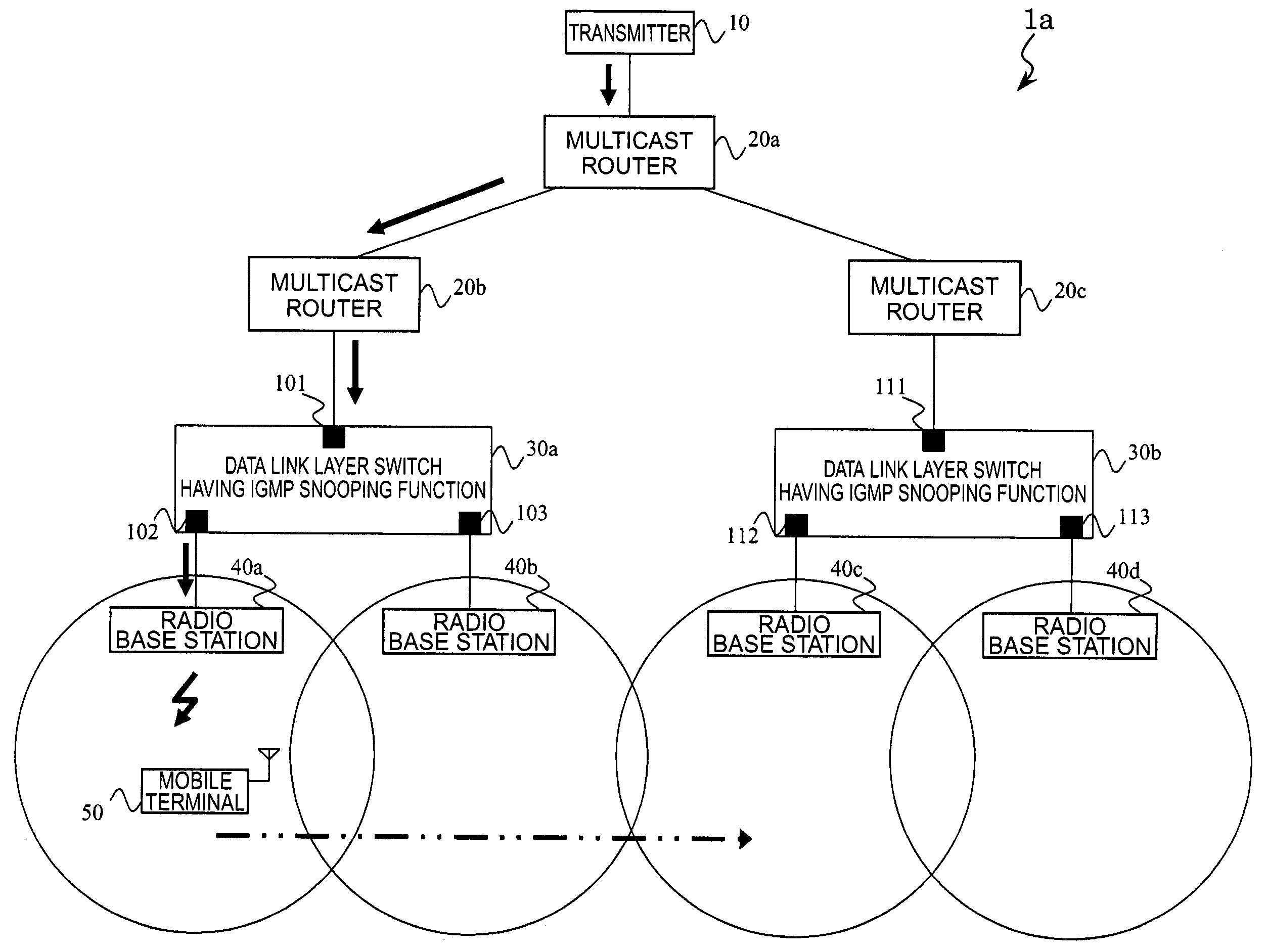
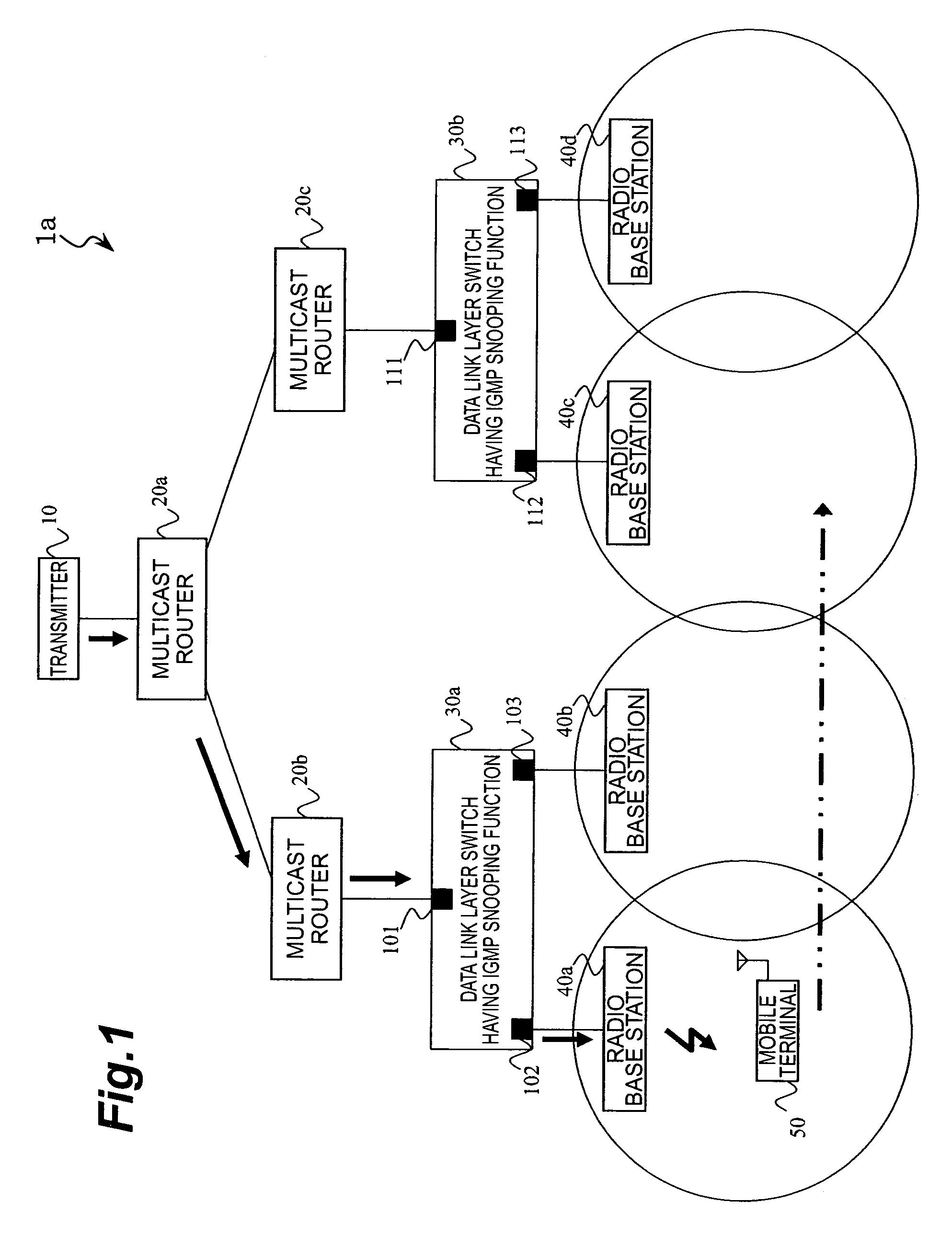
[0108]FIG. 1 is a conceptual view of a mobile communication system 1a according to a first embodiment of the invention. The mobile communication system 1a includes a transmitter 10 which transmits multicast packets using multicast communication, multicast routers 20a, 20b, and 20c which copy and distribute multicast packets from the transmitter 10, data link layer switches 30a and 30b having an IMGP snooping function for making a copy of a packet distributed from a multicast router and distributing it only to a port which has a receiver downstream thereof, and radio base stations 40a, 40b, 40c, and 40d which transmit a packet distributed from a data link layer switch to a radio network downstream thereof.

[0109]The multicast router 20a is connected to the transmitter 10. The multicast routers 20b and 20c are connected to the multicast router 20a downstream thereof, and the multicast routers are provided in the form of a tree. While the present embodiment shows an example in which mul...

second embodiment

[0140]FIG. 14 is a conceptual view of a mobile communication system 2a according to a second embodiment of the invention. In this embodiment, substitute servers 60a and 60b which transmit a request for withdrawal from a multicast group on behalf of a mobile terminal 50 are provided downstream of multicast routers 20b and 20c. When the substitute server 60a or 60b receives a request for withdrawal from a multicast group from the mobile terminal 50, it transmits a request for withdrawal from the multicast group to the multicast router to which the server itself is connected.

[0141]In FIG. 8 described above, when the multicast router connected to the mobile terminal 50 is switched, the mobile terminal 50 transmits a request for withdrawal from the multicast group directly to the previous multicast router 20b. In the present embodiment, the mobile terminal 50 transmits a request for withdrawal from the multicast group to the substitute server 60a. Upon receipt of the request for withdraw...

third embodiment

[0142]FIG. 15 is a conceptual view of a mobile communication system 3a according to a third embodiment of the invention. While only one data link layer switch is connected downstream of one multicast router in the above description, a plurality of data link layer switches may be connected in the form of a tree as shown in the drawing. Each data link layer switch independently performs processes associated with a multicast distribution management table of itself by examining the path establishing requests and the presence check requests as described above, and the multicast packets can be thus distributed only to paths in which receivers exist.

[0143]As described above, in each of the above embodiments, when the mobile terminal 50 detects that the radio base station connected to the same has been switched, it examines whether the multicast router connected to the same has been also switched. When the connected multicast router has not changed, the mobile terminal 50 sequentially trans...


PUM


Abstract

It is an object of the present invention to provide a mobile communication system capable of shortening a delay time preceding the reception of a multicast packet at a radio base station which has been reached by a movement of a mobile terminal. The mobile communication system includes a multicast router, a data layer link switch, a radio base station, and a mobile terminal. In cases where the mobile terminal detects switching of the radio base station but does not detect switching of the multicast router, a path establishing request, a withdrawal request, and another path establishing request are sequentially output. When the switching of the radio base station and the switching of the multicast router is detected, a path establishing request is transmitted to the new multicast router, and a withdrawal request is transmitted to the previous multicast router thereafter.

Description

BACKGROUND OF THE INVENTION[0001]1. Field of the Invention[0002]The present invention relates to a mobile communication system, a mobile terminal, and a mobile communication method.[0003]2. Related Background Art[0004]In the present specification, the term “transmission” is defined as generating and transmitting a packet to an apparatus itself, and the term “distribution” is defined as transmitting (and copying, if necessary) a packet generated by an another apparatus to a slave apparatus.[0005]In a network (IP network) utilizing an IP (Internet Protocol) in a broad sense such as ICMP (Internet Control Message Protocol) and IGMP (Internet Group Management Protocol), a transmitter can perform multicast communication (IP multicast) for transmitting data of files and moving pictures to a plurality of receivers. A procedure for managing a multicast group utilizing IGMP is defined in the IFTF (Internet Engineering Task Force) RFC (Request for Comments) 1112.[0006]In such multicast commun...

Claims


Application Information

Patent Timeline
Patent Type & Authority Patents(United States)
IPC IPC(8): H04Q7/00H04Q7/24H04L12/28H04L12/56H04L12/18H04L12/46H04L45/16H04L45/851H04W4/06H04W28/00H04W36/08H04W40/34H04W40/36H04W80/04
CPCH04L12/189H04L45/00H04W72/005H04L45/16H04L12/1854H04W36/0055H04W40/36H04W36/0007H04W72/30H04L45/851
Inventor MORITANI, YUKIATSUMI, YUKIO
Owner NTT DOCOMO INC
Learn More