Fast, auto-cropping, bi-directional multi-resolution scanner apparatus, system and software therefor

Inactive Publication Date: 2008-07-08
PRIMAX ELECTRONICS LTD
View PDF9 Cites 13 Cited by
  • Summary
  • Abstract
  • Description
  • Claims
  • Application Information

AI Technical Summary

Benefits of technology

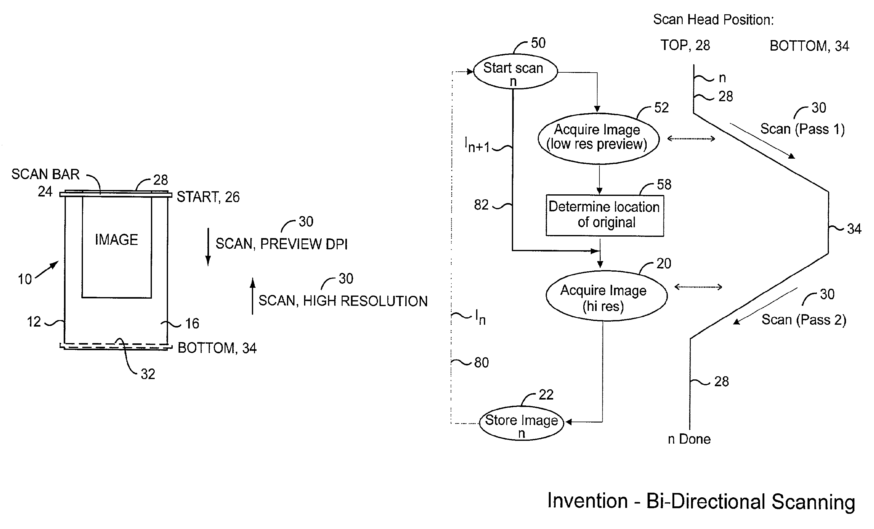
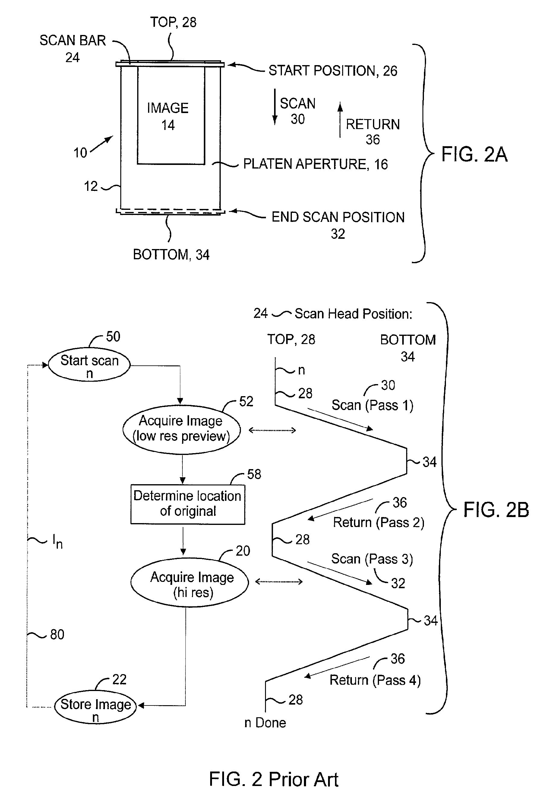
[0017]The scanner apparatus and software system of the invention thus reduce the time necessary for scanning by reducing the overall distance the scanner bar must move. Typical scanners require the scanner bar to move from the starting location, to the end of the flatbed, back to the start, and again to the end of the flatbed to complete the high-resolution scan. At that point, the scanning is done, but the scanner bar must return to the starting location for the next image to scan, i.e. 4 passes to reload for the next item. Thus, present scanners need 4x passes per image, while the inventive scanner / software system only requires 2x for the first image, where x is the number of images to be scanned for the first image, and only single passes for subsequent similarly cropped images. The inventive system reduces the number of steps to a maximum of two: the scanner bar moves to the end of the flatbed and returns. The software of the invention reads the high-resolution image data on the 2nd pass from the bottom of the image to the top and displays the final image in that order, much faster than present scanners do. For example, in current B&W scanning of an 8½×11″ image at 600 dpi the total time from start to reload to the next image is on the order of from about 42-67 seconds. In contrast, in the inventive system the image is scanned and displayed in about 37 seconds, some 7-30 seconds faster than a conventional scanner. In multiple image scanning, since the time for the two return passes and the preview pass is eliminated the productivity is increased from 20 to 300% or more.
[0019]Likewise, when cropping is not required, the inventive scanner system can significantly reduce the time required to scan multiple documents. When a user wants to acquire a stack of x images, the scanner can acquire the first image on its pass from top to bottom, the second image from bottom to top and so on, reducing the wait for the scanner head to return home between scans. This dramatically increases productivity, especially on scanners with a limited power budget, e.g., buss powered devices (USB), wherein the lower power limits the return speed of the scanner head. For example a bus-powered USB scanner is limited to operation at about 500 mA, which is low for a stepper motor, so the scan speed is slower.

Problems solved by technology

However, the superior imaging quality typically results in long scan times and slow imaging speeds.
Because of limitation in the communication speed with the hose, high-resolution scans take a long time, with typical scanners on the market presently taking two minutes or more to complete a single pass at the highest resolution for the full length of the scanner platen (typically 11.69″).
For example, most scanners rated at “1200 dpi” resolution are limited to 600 dpi or less due to optical constraints.
Although some scanners may have a relatively fast return feature in which the non-scanning return to the start position is faster than scan, that return time is still wasted wait time.
CIS heads are slower than CCD, and for large color photo images, the data files can be very large, with consequently slow transfer.
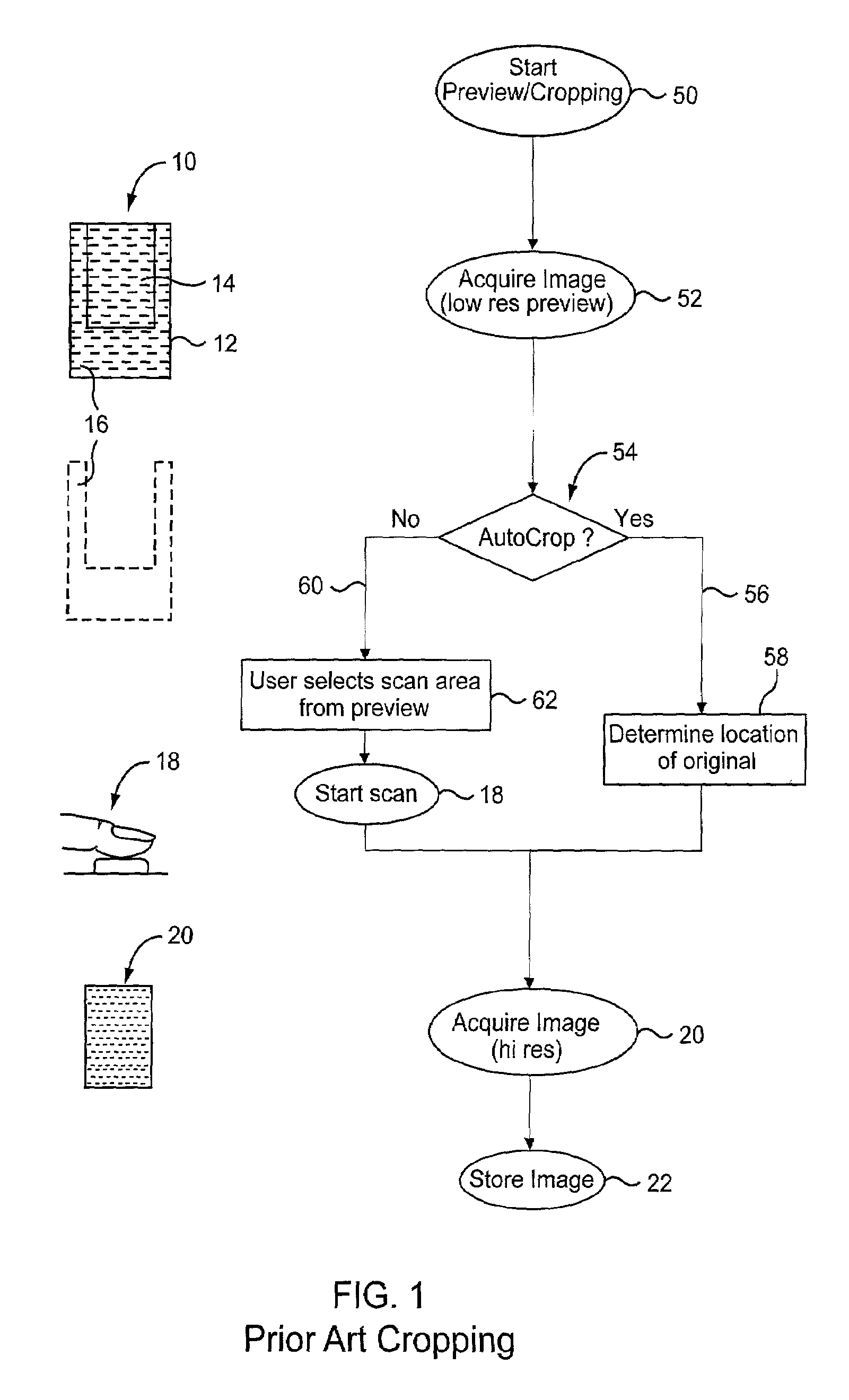
A serious disadvantage of the present scanning / cropping technology arises from the number of passes that the scanner bar must take in order to acquire and render the final high-resolution, useable image on screen for saving to a data file.
Where there are multiple images to acquire, this process takes a very long time, and adds significant cycle wear to the scanner hardware.

Method used


Image

  • Fast, auto-cropping, bi-directional multi-resolution scanner apparatus, system and software therefor
  • Fast, auto-cropping, bi-directional multi-resolution scanner apparatus, system and software therefor
  • Fast, auto-cropping, bi-directional multi-resolution scanner apparatus, system and software therefor

Examples


Embodiment Construction

[0024]The following detailed description illustrates the invention by way of example, not by way of limitation of the principles of the invention. This description will clearly enable one skilled in the art to make and use the invention, and describes several embodiments, adaptations, variations, alternatives, and uses of the invention. The description includes what are presently believed to be the best modes of carrying out the invention.

[0025]In this regard, the invention is illustrated in several figures (and tables where included), and is of sufficient complexity that the many parts, interrelationships, process steps, and sub-combinations thereof simply cannot be fully illustrated in a single patent-type drawing or table. For clarity and conciseness, several of the drawings show in schematic, or omit, parts or steps that are not essential in that drawing to a description of a particular feature, aspect or principle of the invention being disclosed. Thus, the best mode embodiment...


PUM


Abstract

Bi-directional multi-resolution scanner having software / firmware for 1- to 2-pass high resolution scanning, enabling the scanner to capture and render image data both the standard direction, top to bottom pass, as well as the return direction, that is, bi-directional scanning, in contrast to prior art scanners which return to the start position after each pass without reading (scanning). Typical current B&W scanning of an 8½×11″ image at 600 dpi takes a total time from start to reload to the next image of on the order of 42-67 seconds. In contrast, the inventive system scans and displays the high resolution image in about 37 seconds, some 7-30 seconds faster than a conventional scanner. In multiple image scanning, since the time for the two return passes and the preview pass is eliminated, the productivity is increased from 20 to 300% or more. Since multiple non-scan return passes are eliminated, the inventive system is also a substantial improvement for limited power bus devices.

Description

CROSS REFERENCE TO RELATED APPLICATIONS [0001]This application is a Continuation of U.S. patent application Ser. No. 09 / 956,373 filed Sep. 17, 2001 now abandoned and entitled FAST, AUTO-CROPPING, BI-DIRECTIONAL MULTI-RESOLUTION SCANNER APPARATUS, SYSTEM AND SOFTWARE THEREFOR, which is related to Provisional Application Nos. 60 / 233,528 and 60 / 239,652 filed Sep. 19, 2000 and Oct. 11, 2000, respectively, by the same inventors, both of which applications are entitled FAST, AUTO-CROPPING, BI-DIRECTIONAL MULTI-RESOLUTION SCANNER APPARATUS, SYSTEM AND SOFTWARE THEREFOR, the priority of which are claimed under 35 USC § 119. The entire contents of the above-mentioned applications is incorporated herein by this reference.FIELD OF THE INVENTION [0002]The invention relates to apparatus and methods for image acquisition. More particularly, the invention is directed to the use of desktop image acquisition peripherals, primarily a bi-directional scanner mechanism to preview scan and simultaneously...

Claims


Application Information

Patent Timeline
IPC IPC(8): H04N1/04H01L27/00H04N1/387H04N1/10H04N1/193
CPCH04N1/00702H04N1/00708H04N1/00737H04N1/00758H04N1/00816H04N1/04H04N1/0455H04N1/1017H04N1/1039H04N1/3873H04N1/0408H04N2201/0416H04N1/193
Inventor OS, RONBLAIR, JOHN
Owner PRIMAX ELECTRONICS LTD
Why Eureka
Try Eureka