Rotating irradiation apparatus
a technology of rotating irradiation apparatus and rotating axis, which is applied in the direction of instruments, nuclear engineering, and radiation therapy, etc., can solve the problems of inaccurate irradiation position, factor cannot be removed, and the rotational axes of the radial support device are not fully parallel to the front and rear rings, so as to reduce the three-dimensional whirling of irradiation position, increase the positioning accuracy of ion beam emitted, and accura
- Summary
- Abstract
- Description
- Claims
- Application Information
AI Technical Summary
Benefits of technology
Problems solved by technology
Method used
Image
Examples
first embodiment
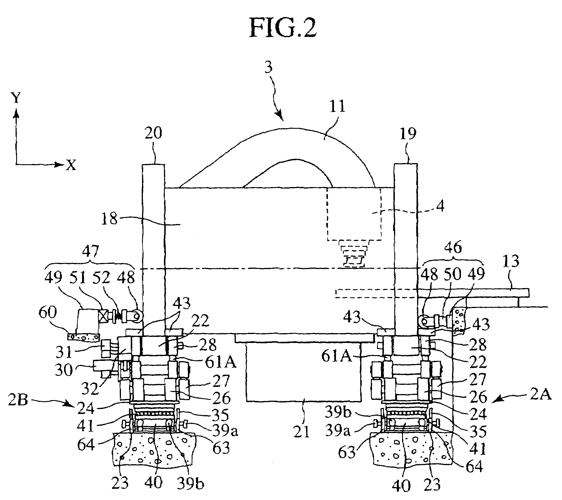
[0032]A rotating irradiation apparatus according to a first embodiment of the present invention will be described with reference to FIGS. 2 to 6A and 6B. The rotating irradiation apparatus of the first embodiment is a structure included in a particle radiotherapy system (or ion beam irradiation system). The rotating irradiation apparatus includes a rotating gantry 3, rotating body support devices 2A and 2B, an irradiation device 4, a beam delivery device 11, a motor (a rotational drive device) 30, a front thrust support device 46, and a rear thrust support device 47. The rotating gantry 3 includes a cylindrical gantry body 18, a front ring (a first annular member) 19 provided on the front end portion of the gantry body 18, and a rear ring (a second annular member) 20 provided on the rear end portion of the gantry body 18. Thus, the front ring 19 is disposed on the side from which a treatment table 13 is inserted into the treatment chamber (not shown) formed within the gantry body 18...
second embodiment
[0072]A rotating irradiation apparatus according to a second embodiment of the present invention will be described with reference to FIG. 7. The rotating irradiation apparatus of the second embodiment is a variation of the rotating irradiation apparatus of the first embodiment, in which the rotating gantry 3 is replaced by a rotating gantry 3A. All other components are similar to those described in connection with the first embodiment. The rotating gantry 3A includes a gantry body 18A and a front ring 19 and a rear ring 20 provided on respective ends of the gantry body 18A. Unlike the gantry body 18 of the first embodiment, the gantry body 18A has a truss structure. Since the gantry body 18A has a truss structure, it has lower rigidity but lighter weight than the gantry body 18. Since the gantry body 18A has lighter weight, the size of the rotating body support devices 2A and 2B can be reduced.
[0073]This embodiment also has the effects described in (1) to (12) above in connection wi...
third embodiment
[0074]A rotating irradiation apparatus according to a third embodiment of the present invention will be described with reference to FIGS. 8 and 9. The rotating irradiation apparatus of the third embodiment is a variation of the rotating irradiation apparatus of the first embodiment, in which the rotating body support devices 2A and 2B are replaced by rotating body support devices 2C and 2D. All other components are similar to those described in connection with the first embodiment. The rotating body support devices 2C and 2D include a radial support device 61C shown in FIG. 8 and a radial support device 61D not shown in FIG. 8, respectively. The radial support device 61C is disposed at the same position as the radial support device 61A shown in FIGS. 3 and 4, while the radial support device 61D is disposed at the same position as the radial support device 61B shown in FIGS. 3 and 4. Unlike the radial support devices 61A and 61B, the radial support devices 61C and 61D include roller ...
PUM
 Abstract
Description
Claims
Application Information
 - R&D
- Intellectual Property
- Life Sciences
- Materials
- Tech Scout
- Unparalleled Data Quality
- Higher Quality Content
- 60% Fewer Hallucinations
Browse by: Latest US Patents, China's latest patents, Technical Efficacy Thesaurus, Application Domain, Technology Topic, Popular Technical Reports.
© 2025 PatSnap. All rights reserved.Legal|Privacy policy|Modern Slavery Act Transparency Statement|Sitemap|About US| Contact US: help@patsnap.com


