Eureka AIR delivers breakthrough ideas for toughest innovation challenges, trusted by R&D personnel around the world.

Modular kiosk

a kiosk and module technology, applied in the field of kiosks, can solve the problems of inaccessible internal hardware components for servicing, inability to change the selection of components or the relative size and shape of components, and high cost and time-consuming to design and build kiosks, so as to achieve the effect of quick change of hardware components

Inactive Publication Date: 2008-05-20
BOWRON JULIAN
View PDF29 Cites 38 Cited by
  • Summary
  • Abstract
  • Description
  • Claims
  • Application Information

AI Technical Summary

Benefits of technology

[0010]A kiosk housing has been invented which allows one to utilize a wide selection of different hardware components within one kiosk housing. This design allows the kiosk designer to select the desired components closer to the time that the kiosk is assembled. This new kiosk also allows one to readily change hardware components after the kiosk is in the field, without the need for cutting, grinding or re-machining.

Problems solved by technology

A limitation of the prior art kiosks is that the selection of components utilized within the kiosk must be defined prior to design and fabrication of the kiosk housing.
Furthermore, once the kiosk housing has been fabricated, it is not possible to change the selection of components or the relative size and shape of components without rebuilding or significantly altering the housing by cutting, grinding or re-machining.
It is expensive and time consuming to design and build kiosks due to the need to create a new design for the kiosk housing each time a new set of hardware components or functions are required.
Another limitation of kiosks of the prior art is the inaccessibility of the internal hardware components for servicing.
However, positioning a number of hardware components in a compact enclosure creates problems for servicing.

Method used


Image

  • Modular kiosk
  • Modular kiosk
  • Modular kiosk

Examples


Embodiment Construction

[0036]As used herein, “kiosk housing” refers to housing which allows user access to user interface portions of hardware components while preventing public access to fragile or removable portions of the components, thereby making it possible to provide the user interface equipment to the public for their use in an unsupervised or semi-supervised setting. Service access to the internal components of the housing is necessary to provide maintenance and to replenish consumable supplies, such as paper.

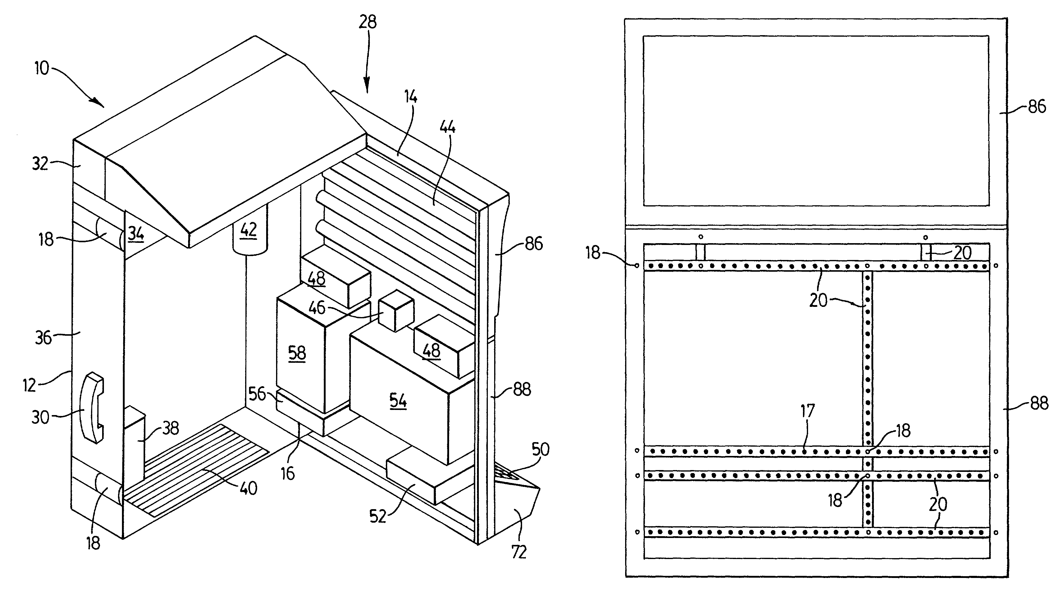
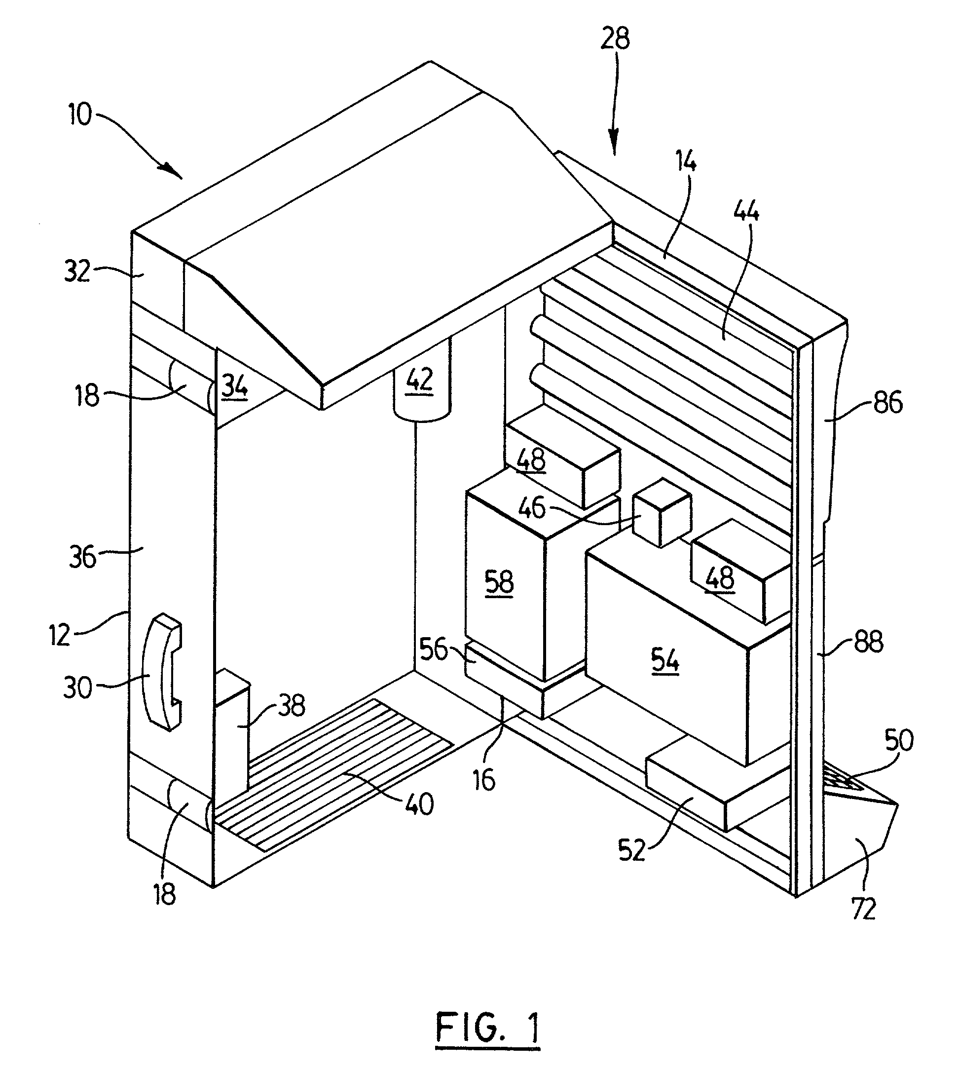
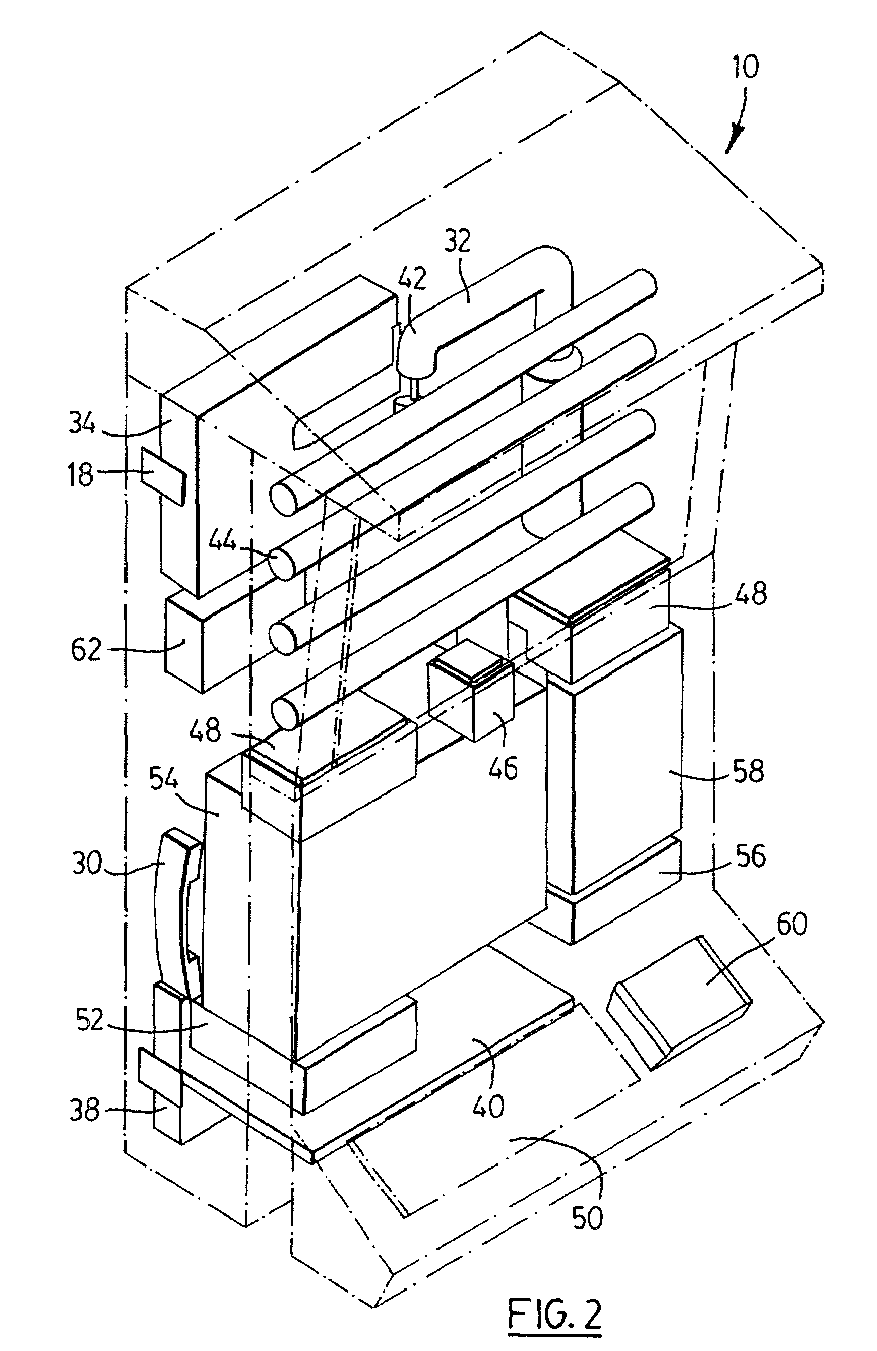
[0037]As seen in FIG. 1, the kiosk housing 10 has a base cabinet 12. Fastened to cabinet 12 by a hinge 16 at one vertical edge, and fasteners 18 opposite, is face frame 14. Face frame 14 is, in turn, fastened to and supporting upper frame 86 and main frame 88. In an alternative embodiment, as shown in FIG. 8H, the face frame may be integral to main frame 88.

[0038]As seen in FIG. 7, an arrangement of cross members 20 are fastened to main frame 88 and to other cross members 20 by fasteners 18....


PUM


Abstract

An automated kiosk has (a) a cabinet; (b) a face frame releasably securable to the cabinet; (c) a plurality of cross members secured to the face frame; and (d) a plurality of hardware components releasably secured to the cross members. The hardware components may be sized and configured such that they project substantially directly inward into the cabinet when the face frame is secured to the cabinet. A method of modifying a kiosk of the invention, comprises (a) removing a hardware component or a faceplate from the kiosk; (b) repositioning a cross member on the kiosk; and (c) installing a new hardware component on the kiosk. A method of constructing a kiosk of the invention comprises (a) assembling a cabinet to a face frame; (b) receiving an order which designates the hardware components required for the kiosk; (c) securing a plurality of cross members to the face frame in a configuration suitable for receiving the designated hardware components; and (d) securing the designated hardware components to the cross members.

Description

CROSS-REFERENCE[0001]This patent claims priority from U.S. provisional application No. 60 / 264,010 filed Jan. 26, 2001, entitled Modular Kiosk.FIELD OF THE INVENTION[0002]The present invention relates to the field of automated kiosks.BACKGROUND OF THE INVENTION[0003]Electronic kiosks are devices which consist of two groups of parts, namely (1) electronic hardware components and (2) a housing for the components.[0004]With respect to the hardware, the programmability of digital computers means that a system consisting of a monitor, with a pointing device such as a touchscreen or a touch pad and / or keyboard, and a computer (CPU), can perform a variety of functions. If the basic system is expanded by adding a printer, camera, speakers, a microphone, card readers, or other peripherals, and is connected to remote information sources by wire or wireless means, it can perform a wider variety of tasks, including e-mail, videoconferencing and database access.[0005]The purpose of the kiosk hous...

Claims


Application Information

Patent Timeline
IPC IPC(8): A47B81/06E04H1/12G07F9/10G09F27/00H05K5/02
CPCG07F9/10G09F27/00
Inventor BOWRON, JULIAN
Owner BOWRON JULIAN
Why Eureka
Eureka Blog
Learn More