
Variable optical-property element and optical apparatus including the same

a technology of optical components and elements, applied in the field of variable optical components, can solve the problems of inability to move the whole or a part of the lens system, low transmittance, and small amount of transmitted light, and achieve the effect of simple structure, no loss of light amount, and easy modification of optical properties

Inactive Publication Date: 2008-05-06
OLYMPUS CORP
View PDF53 Cites 42 Cited by
  • Summary
  • Abstract
  • Description
  • Claims
  • Application Information

AI Technical Summary

Benefits of technology

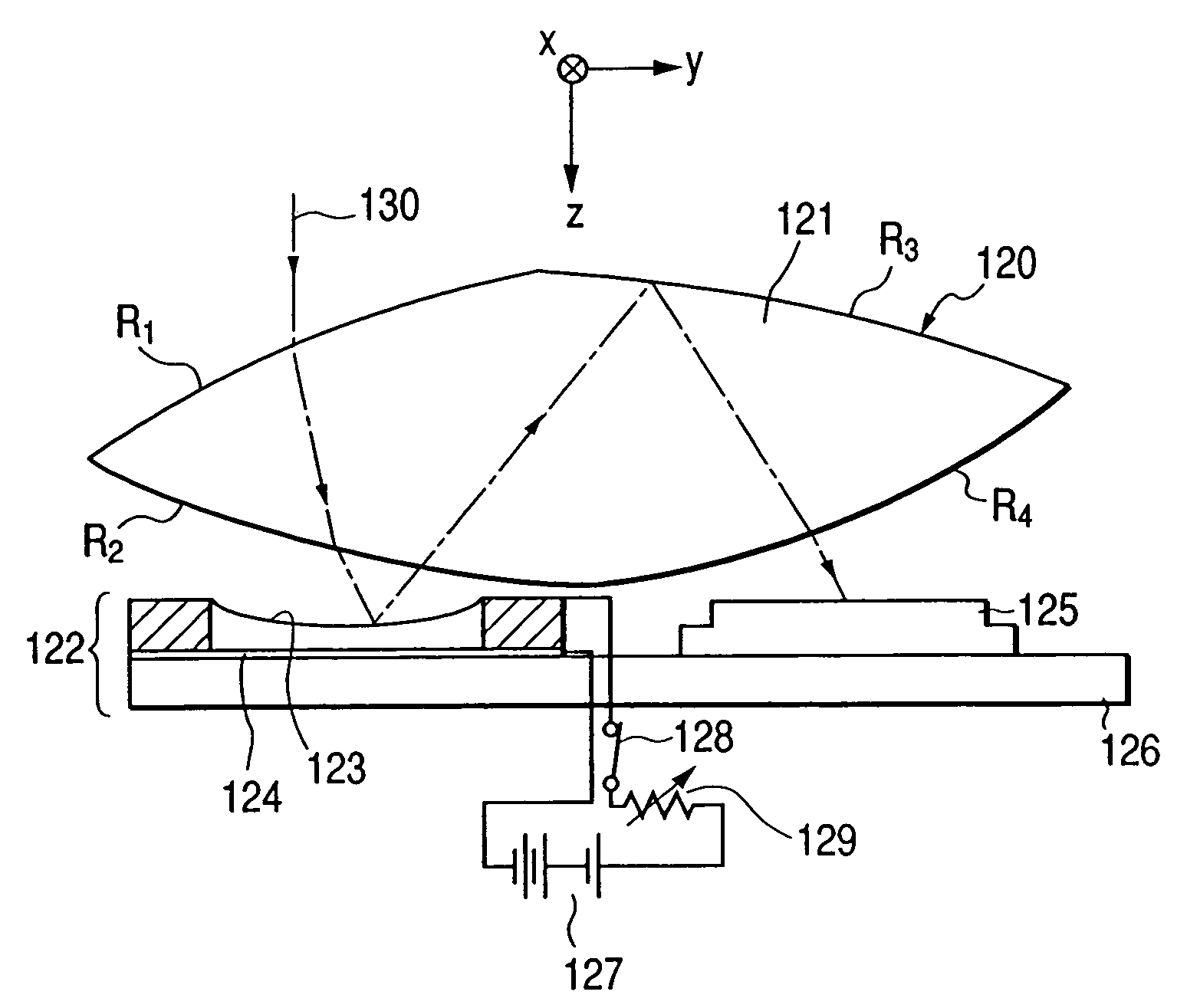
[0020]It is, therefore, an object of the present invention to provide a variable optical-property element in which its structure is simple, there is essentially no loss in the amount of light, operation can be performed at a low voltage, and optical properties can be changed.
[0021]It is another object of the present invention to provide a variable optical-property element, such as a variable focal-length lens, variable focal-length diffraction optical element, or variable deflection-angle prism, which is constructed to raise the efficiency of use of light and to reduce time required to change optical properties such as a focal length, is effectively applicable to various optical products, and has exceptional versatility.
[0022]It is another object of the present invention to provide an imaging device having a small-sized optical system in which optical properties can be changed and aberrations are favorably corrected by adding a curved surface to a variable optical-property element.
[0023]It is another object of the present invention to provide an imaging device which has a variable optical-property element and is designed to correct the fluctuations of aberration and flare caused when optical properties are changed.

Problems solved by technology

However, for an electronic endoscope which is required to be subminiature or the eye of a micromachine, it is impossible to move the whole or a part of a lens system.
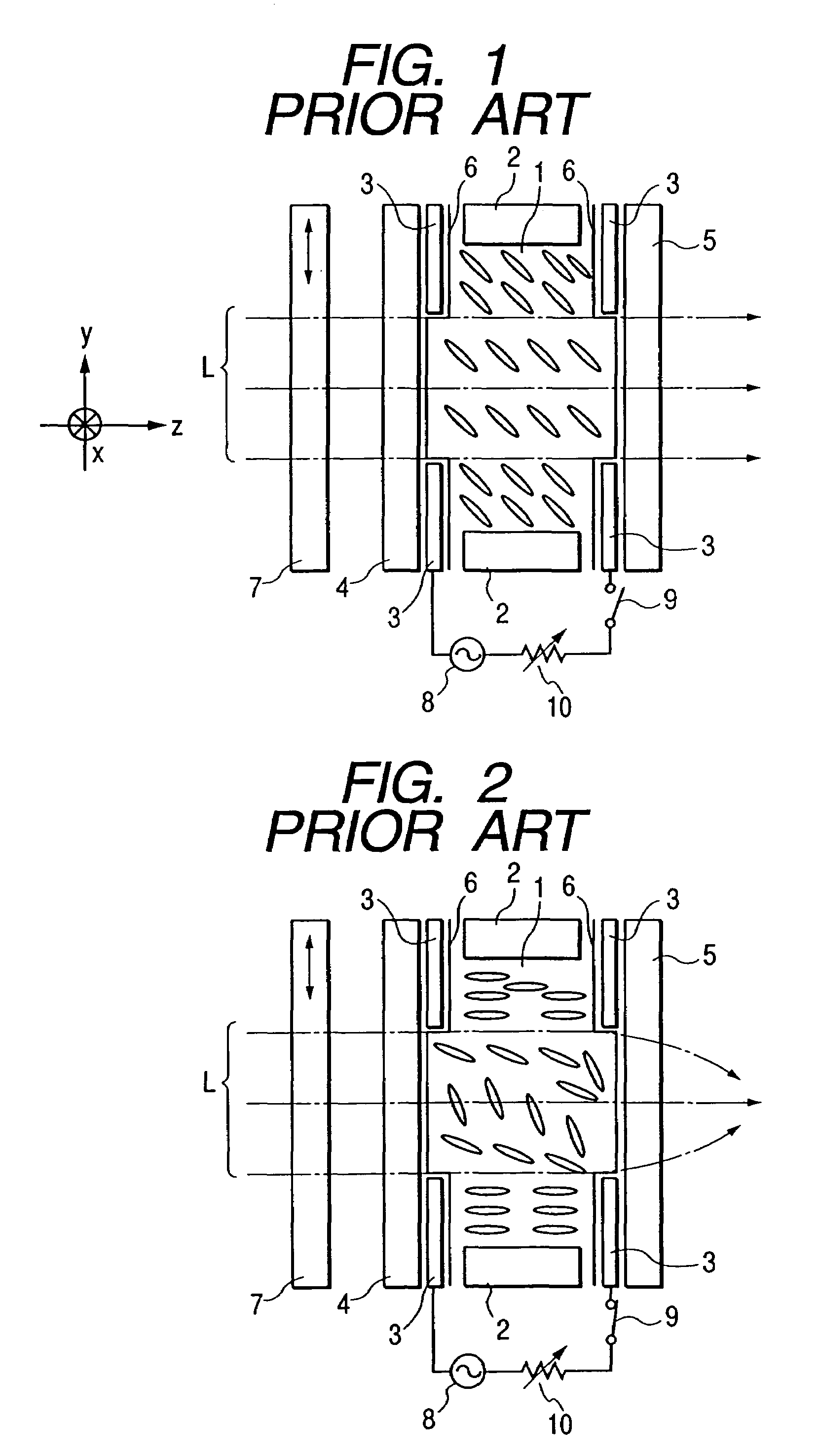
However, this conventional liquid crystal lens, which needs the polarizing plate 7, has the drawback that the amount of transmitted light is so small that a transmittance is as low as 30-40%, and applicable products are highly limited.
Furthermore, a conventional variable focal-length lens has a mechanically complicated structure that because a lens made by grinding glass is used and the focal length cannot be changed by the lens itself, a part of a lens unit must be moved along the optical axis as in the zoom lens of a camera to change the focal length.
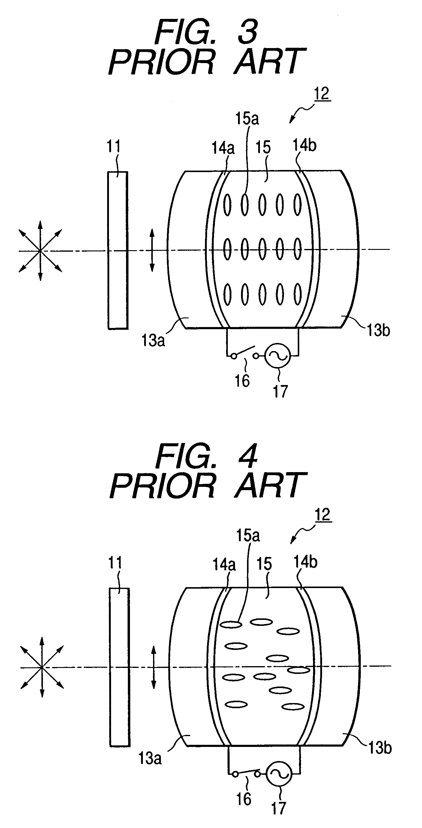
Hence, the optical system has the disadvantage that the amount of light transmitted through the polarizing plate 11 to enter the liquid crystal lens 12 is reduced and the efficiency of use of light is impaired.
Consequently, there is an additional disadvantage that products to which the optical system is applicable are limited and its versatility is lost.
Furthermore, there is another disadvantage that much time is required to change the focal length.
However, the use of only the variable optical-property element, which causes spherical aberration, distortion, and chromatic aberration, is unfavorable.
In addition, the variable optical-property element has the drawback that when its optical properties, for example, the focal length is changed, aberration fluctuates or flare-increases.
This optical system, however, has the disadvantage that the shape of the curved surface is abnormal, and thus when the optical element is moved for the zooming and focusing operations, a mechanical structure such as a moving mechanism becomes complicated.

Method used


Image

  • Variable optical-property element and optical apparatus including the same
  • Variable optical-property element and optical apparatus including the same
  • Variable optical-property element and optical apparatus including the same

Examples


Embodiment Construction

[0108]Before undertaking the description of the embodiments, it will be expedient to explain the definitions of terms employed in the present invention. An optical apparatus used in the present invention refers to an apparatus including an optical system or optical elements, or a part of this apparatus. The optical apparatus need not necessarily function by itself. That is, it is may be thought of as a part of an apparatus or a unit.

[0109]The optical apparatus includes an imaging device, an observation device, a display device, an illumination device, and a signal processing device. The imaging device refers to, for example, a film camera, a digital camera, a TV camera, a VTR camera, or an electronic endoscope. The observation device refers to, for example, a microscope, a telescope, spectacles, binoculars, a magnifier, a fiber scope, or a finder. The display device includes, for example, a liquid crystal display, a viewfinder, a head mounted display, or a PDA (personal digital assi...


PUM

PropertyMeasurementUnit
Magnetic fieldaaaaaaaaaa
Electric propertiesaaaaaaaaaa
Symmetryaaaaaaaaaa

Abstract

A variable optical-property element includes a liquid crystal the pitch of twist is less than 60 times the wavelength of light used, so that a spatially uneven electric or magnetic field or temperature is applied to the liquid crystal to thereby form an index distribution, and the electric or magnetic field or the temperature is changed to thereby alter the index distribution. In this way, the variable optical-property element is capable of changing its optical properties as a liquid crystal lens and is used in an optical apparatus.

Description

[0001]This application relies for priority upon Japanese Patent Application Nos. 10-161198 filed Jun. 9, 1998, 10-198073 filed on Jun. 30, 1998, 10-198080 filed on Jun. 30, 1998, 10-198155 filed on Jun. 30, 1998, 10-198164 filed on Jun. 30, 1998, 10-300296 filed on Oct. 8, 1998, 10-300299 filed on Oct. 8, 1998, and 10-349311 filed Nov. 25, 1998, the contents of all of which are incorporated by reference herein.BACKGROUND OF THE INVENTION[0002]1. Field of the Invention[0003]This invention relates to a variable optical-property element capable of changing optical properties, such as a variable focal-length lens, variable focal-length diffraction optical element, variable deflection-angle prism, or variable focal-length mirror, and in particular, to an optical apparatus including the variable optical-property element.[0004]2. Description of Related Art[0005]The focusing operation of a zoom lens system or an imaging device is usually performed by mechanically moving lenses. However, for...

Claims


Application Information

Patent Timeline
IPC IPC(8): G02B17/00G02B15/14G02B3/02
CPCA61B1/00096A61B1/00188A61B1/0019G02C7/101G02F1/29G03B13/12G03B17/20G02B3/14G02F1/1334G02F1/13768G02F1/1397G02F2001/13775G02F2001/294G02F2203/18G02F1/13775G02F1/294
Inventor NISHIOKA, KIMIHIKO
Owner OLYMPUS CORP
Learn More