High frequency power amplifier and transmitter

a power amplifier and high frequency technology, applied in the direction of amplifiers, amplifiers with semiconductor devices/discharge tubes, dc amplifiers with modulators, etc., can solve the problems of cellular phones continuously miniaturizing, difficult to use complicated techniques, and practically problematic inventions, so as to suppress an increase in the overall power consumption, increase the power supply voltage applied, and reduce distortion.

Inactive Publication Date: 2008-05-06
SONY MOBILE COMM INC
View PDF3 Cites 64 Cited by
  • Summary
  • Abstract
  • Description
  • Claims
  • Application Information

AI Technical Summary

Benefits of technology

[0011]In accordance with an output from the comparator, the power converter circuit selectively outputs the first voltage and the second voltage higher than the first voltage based on the power supply voltage. Specifically, when an envelope signal becomes higher than the reference signal, the circuit can change the power amplifier's power supply voltage. As a result, it is possible to decrease the distortion of a transmission signal in the maximum momentary power portion.
[0015]The high frequency power amplifier and the transmitter according to an embodiment of the present invention allows the maximum momentary power portion for an envelope of a signal to be amplified to increase a power supply voltage applied to the power amplifier. This makes it possible to decrease the distortion occurring in the maximum momentary power. Only the maximum momentary power portion dynamically controls to increase the power supply voltage, thus slightly suppressing an increase in the overall power consumption.

Problems solved by technology

However, cellular phones are continuously miniaturized.
There has been the chronic problem that using a complicated technique is difficult.
However, the invention is practically problematic because it is very difficult for the linearizer to match its temperature characteristic and the like with those of the power amplifier subject to the distortion compensation.
However, such power amplifier generates a synthesis noise because transistor outputs are discretely synthesized.
It is difficult to sufficiently decrease the distortion power in the frequency zone where a detuning frequency is large.

Method used


Image

  • High frequency power amplifier and transmitter
  • High frequency power amplifier and transmitter
  • High frequency power amplifier and transmitter

Examples


Embodiment Construction

[0023]Embodiments of the present invention will be described in further detail with reference to the accompanying drawings.

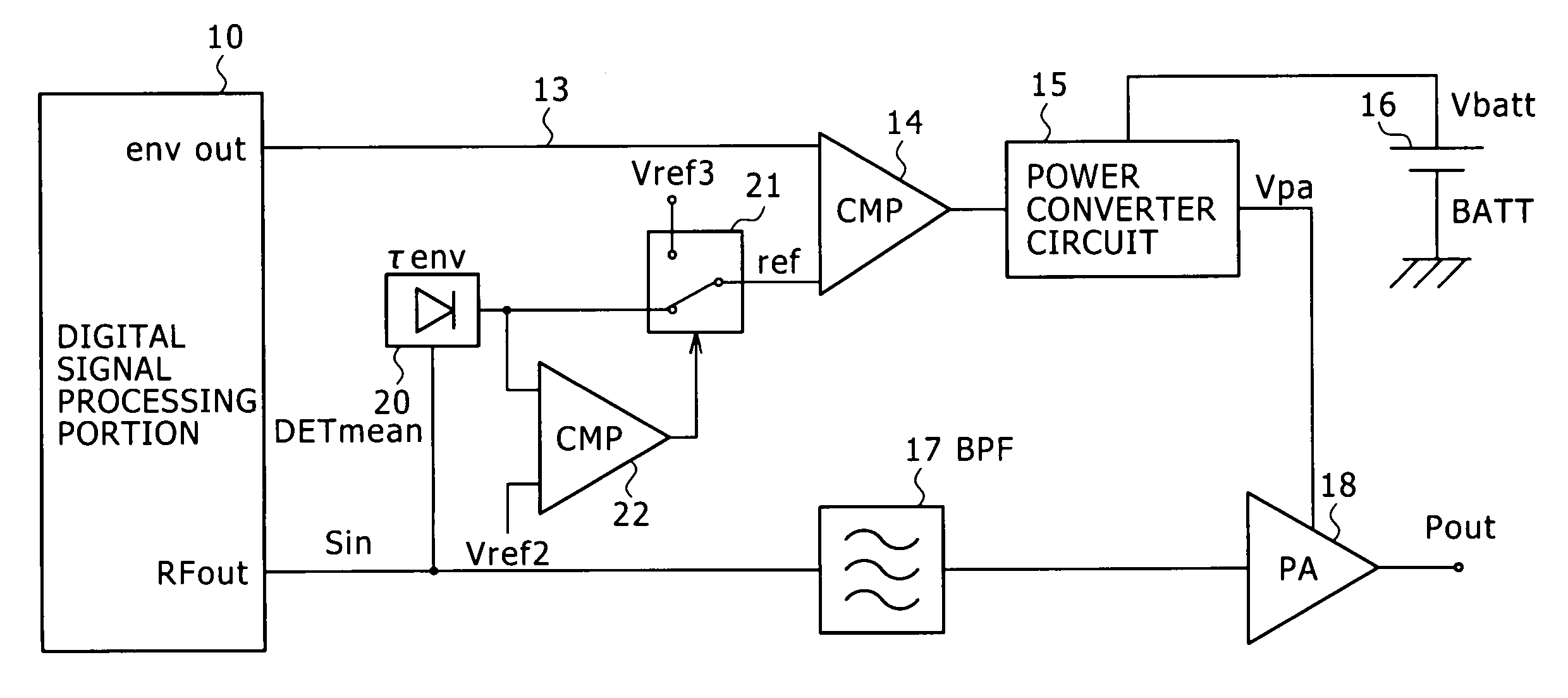
[0024]The following concisely describes the principle that enables the present invention to decrease distortion. A digitally modulated high frequency signal is distorted in the power amplifier because its maximum momentary power portion is subject to the power amplifier's gain compression. Accordingly, when the maximum momentary power portion is subject to the gain compression, increasing a voltage supplied to the power amplifier can decrease the gain compression at that time to improve the distortion.

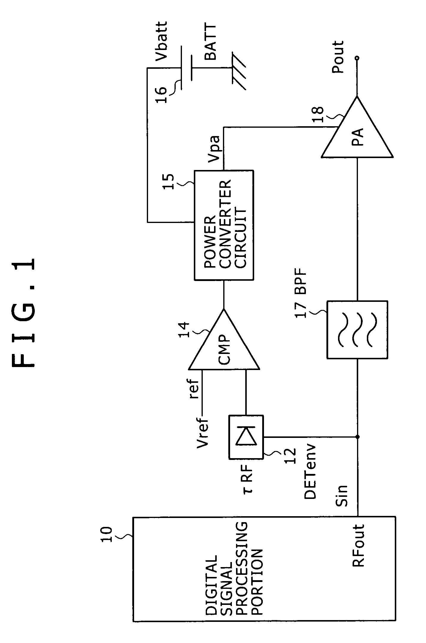
[0025]FIG. 1 is a block diagram showing the configuration of a transmitter including a high frequency power amplifier according to a first embodiment of the present invention. The following describes this configuration. In FIG. 1, a digital signal processing portion 10 outputs a high frequency signal Sin that is generated by digitally modulating data to be transmit...


PUM


Abstract

Disclosed is a digital signal processing portion that amplifies a high frequency signal resulting from digitally modulating data to be transmitted. An envelope detection portion (DETenv) generates the high frequency signal's envelope voltage. A comparator compares this envelope voltage with reference voltage Vref to generate two-state output. According to this two-state output, a power converter circuit converts power supply voltage Vbatt into power and outputs power supply voltage Vpa for a power amplifier. While the envelope voltage is larger than the reference voltage Vref, for example, the power supply voltage Vpa is changed from voltage V1 to V2 (larger than V1). In this manner, there are provided a high frequency power amplifier and a transmitter capable of decreasing distortion of transmission signals by means of a relatively simple technique.

Description

CROSS REFERENCES TO RELATED APPLICATIONS[0001]The present invention contains subject matter related to Japanese Patent Application JP 2004-270804 filed in the Japanese Patent Office on Sep. 17, 2004, the entire contents of which being incorporated herein by reference.BACKGROUND OF THE INVENTION[0002]1. Field of the Invention[0003]The present invention relates to a high frequency power amplifier and particularly to a high frequency power amplifier usable for a transmitter in a communication system such as a cellular phone.[0004]2. Description of Related Art[0005]In recent and future years, code multiplexing is performed for signals transmitted by a so-called third generation cellular phone for the purpose of acceleration and sophistication of data. In this case, there occurs an increase in a ratio of maximum momentary power to an average power (peak factor). Consequently, distortion occurring in a power amplifier increases to increase an adjacent channel interference. There may be a ...

Claims


Application Information

Patent Timeline
Patent Type & Authority Patents(United States)
IPC IPC(8): H03F3/38
CPCH03F1/02H03F1/0205H03F1/025H03F1/32H03F2200/102H03F2200/78H03F2200/99
Inventor KUSUNOKI, SHIGEO
Owner SONY MOBILE COMM INC
Why Eureka
Try Eureka